Natomas Follies

VSB - very slow build

Friday, May 11, 2018

Rudder Pedals Installed

Earlier in the build, 'bout a year ago maybe, I skipped the step for installing the rudder pedal assembly.  I'd read in the VAF forums that it would have to be dropped anyway in order to run coax cables and I didn't want to have to do it twice.  Yesterday I ran the coax from the finish kit, which was easy enough, which took away any excuse I may have had for not installing the pedal assembly.  Or is there?  After several frustrating attempts of trying to get the pedal assembly bolts and washers on in a very difficult-to-reach location I called for backup.  Fortunately my limber, athletic 5'-2" teenage daughter with a black belt in getting at hard-to-reach places was available and able to reach in and get the bolts on for me.

And now rudder pedals are installed!
I have a feeling this won't be the last time I'll need her to build my plane for me.

Tuesday, April 24, 2018

Finish Kit Arrives

Yesterday the finish kit arrived.  Woot! Woot!
That would include:  Canopy, canopy frame, landing gear, wheels/tires, brakes, wiring harness, control rods, control cables, pullys, upper and lower engine cowling, bulkhead panel, and a bunch of other stuff.  Can't wait to get started!


Bending The Longerons (Pictures Only)


Wednesday, December 23, 2015

Lower Firewall Attached

Last weekend I finished putting together and attaching the lower firewall assembly.  The picture below shows the most intimidating step: Smearing fuel tank sealant on the upper flange of the firewall before the firewall "shelf" goes on.  It was only intimidating because it's the first time mixing and using the stuff, but really no big deal.  The one-ounce size ordered from Van's was plenty and had the advantage of both parts of the mix being pre-measured. It even came with a popsicle stick to use as a spatula to mix and spread the stuff around.
And here it is with the firewall shelf attached and riveted.

Once again my truck bed is doing double-duty as a work bench, mostly because I haven't cleaned and organized in a while.  The seat cushions, used to protect the bottom skins from scratches, are from a table set we had when the wife and I first got married. It was cheap and the chairs eventually broke but the seat cushions still come in handy every now and then.  Someday the plane will be on it's own three legs and I'll happily free up limited garage space by tossing the cushions.

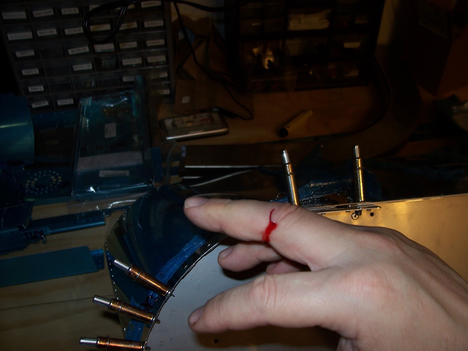
I probably got other nicks along the way but this was the worst so far.  The steel firewall just isn't as finger-friendly as the rest of the parts and skins, made mostly from aircraft aluminum.  I read somewhere that you can't build an airplane without getting at least a little blood on it.

Once the fuel tank sealant cured it was time to add 18 inches of length to the fuselage by attaching the lower firewall assembly with clecos followed by pop-rivets.
Either due to the reflection off the shiny bottom skins, the poor lighting, or just the image quality you get from an old camera, the clecos used to temporarily hold parts together can look kind of strange in the photographs.  Here's a picture of the bottom of the fuselage with all the bottom rivets done and clecos <mostly> removed.
 And here it is with the fuselage turned right side up again.  RV-12 builders should note that you'll want to rivet the "vertical" rivets first before the bottom skin rivets.
It looks a little happier now, doesn't it?

Thursday, November 12, 2015

November Update

Photo courtesy of Gawhdlmuhrt


As you've probably guessed I have lost interest, for the moment, in keeping up this blog in any kind of detailed way.  Even so, I just want to reassure friends and family that I have been making steady progress on building the airplane fuselage, which got underway once garage temperatures dropped into the tolerable range around September.  Building the fuse has actually been a lot of fun so far, addicting even, as one by one individual pieces leave the parts pile on the work table and becomes yet another extension of what looks like a shiny modern art sculpture.  I'll probably return to posting a little more and a little more often as winter comes, but for now I'll just throw up some pics of where I'm at with the fuselage, which covers up to plans sections 20, 21, and 39:


Monday, May 18, 2015

Fuselage Kit Arrives


The red and purple truck came today.  Scheduler said it should arrive sometime between 9:00 and 6:00, which necessitated taking a day off, but the driver actually showed up mid-morning, which made it nice for leaving the rest of the day for chores, honey-dos and a little daddy-nappy.

I was a bit annoyed that the shipping crate was transported on its side when there are "up" arrows clearly painted on the sides of the crate.  At least it was secured with a rope to keep from falling over during shipping.

However the crate arrived undamaged and Van's crating department does such a good job that I think everything packed inside is okay.


Especially since they pack it with a tree's worth of paper to cushion with.

Which my daughter has claimed for her arts and crafts projects.  I estimate that there should be enough there to last 'till college.

Faithful to my miserly tendencies, I rather fancy the idea of using it for everyone's Christmas present wrapping.


We'll see how that works out with the CFO.

Monday, May 4, 2015

Wing Tip Lights

While waiting for the fuselage kit to ship from the Van's factory in Oregon I still had a few things left to do on the wings, namely adding on the fiberglass wing tip light extensions, match drilling rivet holes, making the wire connections, and installing the wing tip nav-strobe lights.  This actually took me a while, although the actual hurdles were mostly mental ones having to transition from working with metal to working with fiberglass and epoxy resin.  To start with, the fiberglass wing tip light extensions were over-sized from the factory molds and had to be trimmed and sanded down to a barely-there scribe line on the fiberglass.  Rivet holes were then drilled at various locations around the outside edges of the fiberglass extension, and then those holes were used to guide rivet holes into the wing tip close-out skin.  After that, any gaps along the edge of the wing tip edge rib where the extensions wrap around is filled with an epoxy-flocking fiber mixture called flox.  Flock + epoxy = Flox.  Cute huh?  On the right wing the gap was mostly at the front end of the extension, and on the left wing it mostly at the aft end.  I'm not sure if the gaps are due to irregularities in the factory fiberglass molds or what.  I wouldn't rule out first-time builder error, but I did try to sand it so that it matched the edge rib as close as I could, which required some trial and error fit-sanding.  Here's what the gap on the right wing tip extension looked like (wing is upside-down, btw):


Flocking fibers, or "flock" are cotton fibers ground up into a flour and not available locally.  Only a few tablespoons of the stuff were needed to fluff up the two-part epoxy I picked up at Home Depot to the desired consistency for use on the extensions but the smallest amount you can get from Aircraft Spruce is one pound, which is probably more than I'll need for the whole plane.  Fortunately it's not very expensive.  As usual shipping from AS cost more than the product.

Here's everything needed for the flox work - car wax, popsicle sticks, table spoon, modeling clay... the usual high-tech airplane builder stuff.
 
So what's the car wax for?  It's a release agent.  It keeps the flox from sticking to the aluminum wing skins and wing-tip rib while hardening and works pretty well.  The picture below shows the stuff smeared all over the wing tip rib.


According to the plans, a small dollop of modeling clay is used to create a recess in the flox for a nut used to fasten the bracket for the wing tip light.  My daughter had some left over from one of her school projects last year, so I didn't have to buy any, but it was a little dry.  So I mixed in some water and waited a couple days and it was ready to use.  Here's where the dollop is placed on the fiberglass extension:

Did I get it in right shape and place?  Not exactly, but it was close enough to be able to get a nut on the back of the nav-light attach bracket with the designated screw, and that's what counts.  I probably shouldn't have made it quite so high ("proud") off the fiberglass 'cause I think it got nudged and smooshed out-of-position a little when I cleco'd the fiberglass extension in place.

Here's how it turned out after adding the flox, letting it harden, and digging out the clay with a small screw driver:

Not as nice as the plans photo, but I guess it'll work.  The two-part epoxy I used had a five-minute set time after mixing the hardener so I didn't have time to make it purty before attaching the extension onto the wing skin with clecos.  Since there is so little time once you mix the two-part epoxy to start the chemical reaction, I couldn't take any pictures.  But all there is to it really is to use a popcicle stick to mix and spread the flox along the edge like peanut butter, cleco the extension on, wipe away any drips, and wait 24 hours.

After the flox hardens, the bottom* rivet holes are drilled, a hole is drilled and filed to pass-thru the connector for the electrical wires, and holes are drilled** for the bracket screws.


*They're actually the top holes - the wing is upside down.

** Be careful!  The holes you want for the bracket screws may not be exactly where the dimple marks in the fiberglass ext. say they should be.


Male and female wiring connectors are attached to the wires coming out of the nav light and wing tip.  More micro-fit pins (male and female).  Had to use a magnifying glass for those.  My eyes just keep getting worse and worse.  I am getting better at crimping micro-fit pins though.  All pin connections were tested with a really good pull on the wire.


With the wiring connected the $400-plus (each!) nav-light is attached to its mounting bracket with a set screw.  Hope I never break this thing - the CFO would kill me.


And here is the right wing, the side that also has the landing light.  The position of the light on the extension turned out slightly better than the left wing, so I hope that's the side that gets scrutinized by other RV builders.


Here's another couple pictures of the right wing extension.  A little blurry, but see how the body of the nav-light makes a smooth transition with the fiberglass extension, which itself transitions smoothly onto the wing skin?
And the ugly gap I showed you at the top of this post?  It's filled in quite nicely.

There's one more task before riveting the light and light extension onto the skin and that's to mask and then caulk a small bead around the edges of the fiberglass extension with a product called ProSeal.  I'm holding off on that step because 1) I don't have any, 2) it's relatively expensive, 3) it doesn't keep very long, and 4) I only need a tiny bit to finish the wing tip lights.  It's kinda disappointing that I can't finish this final task before hanging the wings back up on their ceiling straps, cleaning up, and starting the fuselage kit next week, but that's how it goes sometimes.  If any Sacramento-area (or Davis) RV builders could help a poor airplane builder out with an ounce or two of ProSeal, please let me know.

Friday, March 13, 2015

Ordered Fuselage Kit

Today I mailed off the order form for the next kit in the series, the airplane fuselage kit.  The shipping crate should arrive in about 8 - 9 weeks, just before Sacramento summer weather arrives.  I don't expect to get much done over the summer (too hot in the garage), but who knows, maybe there will be sub-assemblies I can put together indoors without making a mess.

3/24 update:  The notice I received from Van's says that the fuse kit will be shipped the week of 5/11.

Friday, February 27, 2015

First Service Bulletin: SB 14-11-03

Announced recently by Van's Aircraft Company was a Service Bulletin, No. 14-11-03, requiring RV-12 owners to inspect certain wing rivets for signs of wear.  Apparently the demo plane at the factory in Oregon started showing signs that rivets were starting to wear in the wing root area, and so Van's decided that the safe course of action was for the whole RV-12 fleet to be inspected.  If signs of wear are found, then a skin-to-spar doubler is called for to beef up the area, and that's expected to take an hour and a half per wing to install by a qualified airframe mechanic.  Of course you don't have to install the doubler if there's no sign of wear; the plane will probably fly hundreds of hours just fine without showing any of the symptoms described in the SB, it's just that it's relatively easy to do now, cheap (~$20, w/shipping) and installing the doublers will likely prevent future rivet wear problems by making the wing stronger overall.  So I ordered the parts from Vans and got to work removing rivets where doubler plates are to be added at the wing root on the bottom side of the wing.


I didn't get any photos of yours truly removing rivets so I can't show any, but here's one of the bits and pieces of pop-rivets that were drilled out placed next to SB Figure 1, which shows the orientation and location of the doubler.

Step one in removing a pop-rivet is to knock out the leftover piece of mandrel through the bottom of the rivet with a suitably sized punch.  That's the little bits on the right side of the tray picture below.

Step two is to use a 1/8" drill bit to very lightly drill off just the manufactured head of the rivet.  That's the washer-looking thingys in the bottom of the red tray in the picture to the right.

Step three is to push out the shop-formed side of the rivet with a couple taps on a slightly larger punch, shown in the upper left of the tray.

There's 21 pop-rivets to drill out on each wing, and each piece, except the heads, had to be found and removed from inside the wing by reaching through the rib lightening holes and feeling around 'til I found it.  I got most of 'em but unfortunately a couple of the tiny mandrel pieces didn't want to be found.


Once the rivets are removed the SB calls for you to cleco on the doubler and match-drill 42 holes into the bottom wing skin using the doubler as a template, and enlarge 8 existing holes to accept the larger and stronger 5/32" pop-rivets.
As always, appreciation goes to my beautiful wife for taking photos for this blog, buddies who help move the wing from the ceiling to the workbench and back, and for every neighbor who steps up the driveway when the garage is open to ask "Howzitgoin?".

Appreciation also goes to Mr. B for the extended loan of his airplane building tools.  When he loaned me his tools two and a half years ago, included in one of the parts trays was a tiny little ziplock baggy of #30 high-speed "jobber" drill bits, the size used for LP4-3 pop rivet holes.  I almost can't believe they've lasted this long, but they're still cutting just fine so I keep using 'em.  Here's a couple pics of the drilled out holes:

After removing the doubler, clearing away chips and cuttings, deburring holes, and vacuuming out the inside of the wing, the SB has us "chamfer" the edges of the doubler.  I thought the word was "bevel", but what do I know?  Mr. B's belt sander (below) accomplished that task quite nicely.  I think the bevel angle is supposed to be about 45°, but I tried to aim for something closer to 60°, but lightly rounded at the edge.  You don't want a metal edge you can cut paper (or fingers) with.


With the prep work done all that's left is to rivet on the doubler, right?  There's just one little problem.  Can you see it in the picture?

        No?  How about now?

The rivet mandrel for the larger 5/32" rivets broke off above ("proud") of the rivet head.  Which means they had to be filed down flush with the top of the rivet head, which is not fun.  How did that happen?

I think what happened is Van's sent the wrong length of rivets.  SB Figure 6 calls for using "BSPQ-5-2" rivets (also known as "oops" rivets in certain unfortunate contexts), but Van's sent BSPQ-5-4 rivets, according to the parts list.
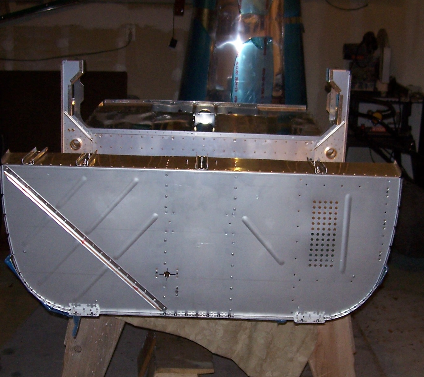
As you can see there are eight 5/32" rivets for each doubler (the rest are "regular" size)
.
Builders take note:  The way you want to do this (having learned the hard way) is, counting from inboard 1, 2, 3, ... 8, do rivet #8 first, before any other rivets.  If the mandrel sits proud of the head, file it down.  Then do #7, then #6, and so on, working your way back to the wing root end.  Take care not to scratch the doubler with the file while you're doing it.  That's the tricky part.

Or you could be smart and just get the correct 5-2 rivets to start with.


After filing down the 5/32" rivets the rest was easy.

Here's the doubler installed on the bottom of the left wing:


And here's the right wing hanging from the ceiling again so I could use the bench for the other wing.  My first SB!

Recall that I said that Van's SB says that installing the doubler should only take 1.5 hours per wing?  It took me about three times longer than that.