Natomas Follies

VSB - very slow build

Tuesday, December 11, 2012

Back in the Saddle

I know.  It's been over a month since I last posted.  Truth is, I just haven't worked that much on the plane.  Lots of yard work and things like that have gotten done on the weekends (with body aches to prove it), but for some reason my enthusiasm for evening work on the plane has wained a bit with the shorter days, despite taking a day or two off to work on it.  I need to get on the ball though.  There'll probably be a scheduled price increase in February on the various kits that Van's sells and I'll want to have my order placed for the RV-12 wing kit before then.  Because of workspace issues I'll also want to have the tailcone finished and stowed away before the big crate full of airplane wing parts arrives at my door.

So what have I done in the last month?  Well, I
 * removed the blue plastic protecting the skins along all the rivet lines,
 * deburred all the rivet holes and edges,
 * bent the edges on the tailcone skins per the plans (not hard, once someone shows you how),
 * fluted the frames to straighten the rivet hole lines, and
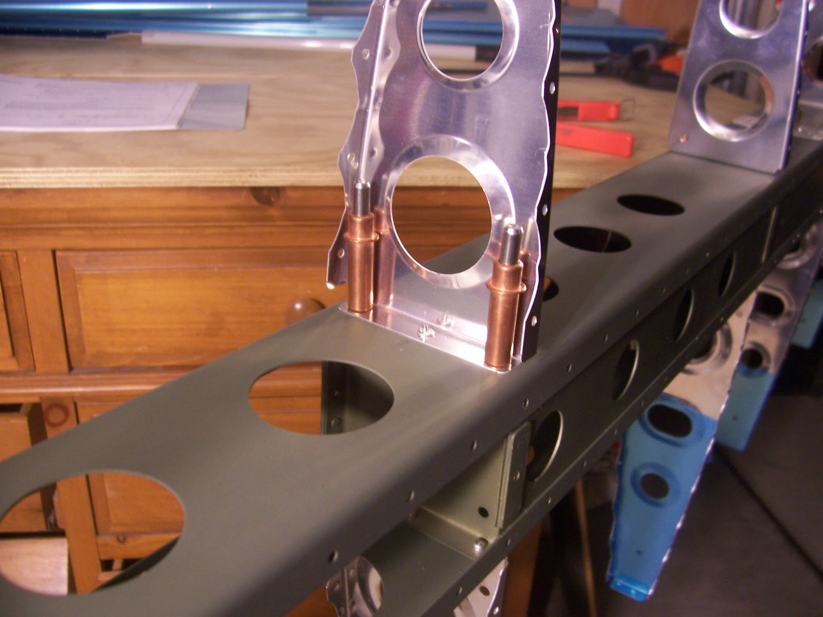
 * fastened together the tailcone frame hoops shown in picture.
The large and medium hoops are easy - a few pop rivets and you're done.  The small hoop, the one that goes at the very aft of the tail cone, required the assistance of my neighbor Ken because there's a doubler plate and six-inch angle fastened with #4 rivets that need to be squeezed, and the pieces are too light to secure firmly while operating the rivet squeezer, which is also awkward to use (for me anyway).  In return I promised to help Ken clean out his second-story rain gutters this weekend.

As you can see, I did manage to mess up the first rivet (bottom row left) by oversqueezing it, I think.  Somehow there ended up being a small gap between the doubler plate and the frame after I squeezed the rivet.  So I drilled it out and, since the hole is now enlarged, ordered some #5 rivets from Aircraft Spruce to use in that hole.  They should arrive any day now.  The other 17 rivets went in pretty well because I took my own earlier advice and only gave each rivet a half-squeeze until all 17 were in, then went back and re-squeezed down to spec.  It also helped a lot having Ken hold the frame steady while I manned the rivet squeezer.  With the exception of the first bottom rivet (soon to be fixed), I'm satisfied with it.
Picture of tail cone frame frame

December 18 update:  The # 5 replacement rivets came in the mail so I could finish the final rivet in the small bulkhead hoop.  You're not supposed to use a Cleaveland Main Squeeze rivet squeezer on 5/32" rivets but I used it anyway and didn't break anything.  Here's the # 5 "oops" rivet next to seventeen # 4s:
It should be okay.  It's deep in the tailcone and faces aft, so no-one will see it anyway.

Saturday, November 3, 2012

You Meet the Nicest People

Step 1 of Section 10 has us "break" the edges on six 8' tailcone skins.   By "break" they mean bend the long edges of the skins a few degrees so that the overlapping edge is flat and snug when the skin is riveted (the clamping pressure of a rivet can cause the edge to lift a little bit).   Due to the geometry of the tailcone (radius is smaller at the back end than the front end) the bend, or "break", increases as you move down the narrow end(s) of the skin(s).  Fortunately there's a handy tool for breaking edges (shown in the picture) that I borrowed from the guy at work.  Apparently it's easy to use once you learn how.  Problem is I don't know how to use it.  Seriously.  Clueless.  Never seen it done before.  The owner of the tool never used it either.  So I put a message out to the Sacramento RVators group to ask for help. 
Right away the group's founder, president, secretary, treasurer, and newsletter editor, Ed Martinson, put me in contact with Kerry Richburg, a retired fellow who flies a beautiful RV-9A he built at Sacramento Executive airport.  Kerry took time out of his morning (he was prepping to fly to Monterey) to introduce me to the edge tool and a few other tools that I'll be needing down the road, including a tube bender and fuel line flaring tool.  The SacRVators group loans them out like a library book so that RV builders don't have to shell out dough for an expensive tool they may only use a few times.  Here's a picture of Kerry and his -9A:
 
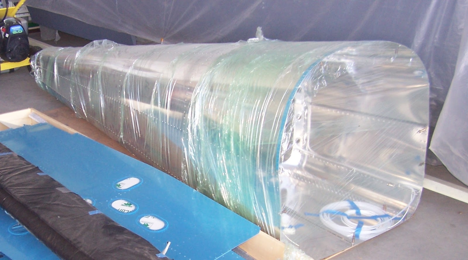
Kerry demonstrated proper technique for breaking an edge and gave me some scrap aluminum to practice with (it's not like you can just pick up 2024-T3 0.020" aluminum at Home Depot, and none came with the kit).  He also passed along info about a flying club called DGA (Damn Good Association) located at the other end of the airport.  The club's hangar is open weekends and anyone can drop by and take the nickel tour of some of the club's 10 different airplanes.  At any given time the club is always rebuilding some vintage aircraft, but the latest project acquired by the club is a partially-completed RV-12.  It seems that the original builder became ill (Alzheimer's or Parkinson's or something like that) and was unable to finish.  So the club bought his partially completed -12 for less than the cost of the kits.  The finished parts include the stabilator, vertical stabilizer, rudder, trim tabs, tail cone, wings, flaperons, and most of the fuselage, all very nicely put together.  Here's a picture of the tail cone, which is the part that I'm just now starting:
 
I asked one of the builders there, Mark Z., how long he thought it would take the club to put the -12 together and he said that they would probably have it flying by April.  Holy c*@p!  He also speculated that, with high fuel prices, it would be a very popular airplane for the club.  The good news is that there's at least one CFI (that's FAA-certified flight instructor you land-lubbers) in the club who will be able to provide the necessary transition training in the -12 before it's my turn to once again "slip the surly bonds".
 
November 2014 Update:
Okay I'm back from the future.  The DGA RV-12 was completed and certified airworthy in July 2013.  Club members flew it around, added wheel pants, and recently had it painted.  Here's a picture of N471PD:
 
Congratulations DGA!

Friday, November 2, 2012

Stabilator is Finished

Section 9 concludes with drilling holes and attaching weights to the counter balance arm.  With five pounds of lead weight on the counterbalance arm, the stabilizer now wants to tip forward except that my helpful assistant (out of the picture) is holding down the stab to prevent that.  After picture-taking the counterbalance arm is taken off and stowed away.
And   we    are    done!
With the stabilator finished it's time to move it to make room to start the next piece. The safe place turns out to be in the family room.  Nice place to store it, don't you think?

The vertical stabilizer and rudder are in the corner.  Together these parts should make interesting conversation pieces just in time for Thanksgiving festivities.

Coming up is Section 10: Tailcone assembly.
I have a feeling this part is going to take a while.

Thursday, November 1, 2012

Halloween Downpour

Our neighborhood was swarmed last night with ninja warriors, vampires, princesses and trick-or-treaters dressed up as teenagers too lazy to put on a costume.  The problem with having generous neighbors is that ghouls and bandits from miles away are bussed in to collect a share of the loot.  Then at 8:30, after my kid returned with her cut of the action and three large bags of candy were just about gone, a storm front moved in that soaked the area for about five or ten minutes.  You could hear the cries and screams a block away.  Heh heh heh.  A steady drizzle afterwards meant that the Halloween blackmail was over and I could open up the airplane factory for a couple hours.

80 rivets later the aft stab skins are attached and it's time to attach the stab horns.
One of the bolt holes on the lower horn did not line up perfectly with the nut plate inside the spar box so I had to elongate one hole slightly in order to get the bolt in the nut plate without risking a cross-threaded bolt.  Really hated to mar the powder coat finish on the steel stab horns but it was necessary since moving the nut plate was out of the question.  I think it will be okay.  I'm probably not the first one who's done this.  If I had a do-over I would have taken much better care to center the nut plates for the horn bolts exactly before the spar box is riveted together.
The stab counterweight arm is put back on temporarily in order to attach lead counterweights, which I'll do tonight.

Thursday, October 25, 2012

Skinning the Stabilator

So moving along last week I drilled holes in the piano hinges for the trim tab.  The drill press I borrowed worked well for that task.  Also finally got around to throwing out the piano hinge that I screwed up on September 12.  The light soft aluminum hinges cut and drill easily and, as you can see, bends easily as well.  Thought about turning it into a Christmas tree ornament but the CFO quickly put the kibosh on that idea upon seeing it sitting on the kitchen counter.
After prepping the hinges it's time to attach the main stabilator skins to the skeleton with clecos and start riveting.  The right skin I did myself but for the left one the assembly was too awkward and bulky so I needed help nudging the forward ribs and skin holes to line up.  Fortunately relatives came over and volunteered to help ("volunteered" - sounds much nicer than "drafted" doesn't it?).

We always start riveting at the leading edge and work our way back.
After a while the rivet tool was getting less and less of a grip on the rivet post and started requiring 7, 8 or 9 squeezes to "pop" the rivet.  Driven to exasperation I disassembled it, sprayed out the barrel with automotive prep clean followed by WD-40, reassembled it and tried it on a rivet.  Better, but it still wasn't getting good bite.  Then I put a washer on the interchangeable nose of the tool and after that it worked perfectly:  squeeze, squeeze, squeeze, POP!

530 pop rivets later the stabilator skins are on!  Keeping things in perspective, however, that's just a dent in the box of 10,000 rivets shipped to me by Vans to build the airplane.

The next step calls for attaching the aft trim tab hinge to the back of the stabilator.  Before riveting I checked to see if the trim tabs would fit by installing the trim tabs and hinge pin.  It was a tight fit but seemed okay so I cleco'd the hinge onto the back of the stabilator with the trim tab still on.  Here's a picture of the control horns where the two trim tab halves meet:

After the test fit the trim tab was removed and the hinge(s) and splice plate were riveted on.  By this point I had "popped" 670 rivets and my hand was sore from all the squeezing on the rivet tool so I took a break from popping any more rivets.

I did, however, cleco on the aft stabilator ribs (4) and skins to see how they would look.  I was concerned with how I would ever get the trim tab hinge pins in once the aft ribs and skins were on.  Reading ahead shows that the hinge pins are sharpened on one end and inserted from the middle by bending it.  The other end is bent into an "L" shape and safety wired in place.  Inserting the hinge pin promises to be a PITA difficult and I wondered why we don't just put the AST trim tab on now while there's still easy access to the hinge pin holes.  Upon further reflection it occurred to me that the inboard aft skin ribs need to be bent over a little to get the rivet tool on the rivets and that would not be possible with the trim tab(s) on.

Monday, October 22, 2012

Stabilator Hinge Brackets

Page 9-7  has us bolting in the stabilator hinge brackets and hinge stops (that's what the 21/32" pieces of alumninum tube were for).  The page has a nice figure that explains everything.  What it does not have, however, is anything reminding you to use a torque wrench.  Apparently you're just supposed to know that you need it.  Indeed, way back on page 5-10 (which also covers topics like canopy protection and scratch removal) it does say to use a torque-wrench on all the bolts.  I suppose I must have read it back in June sometime, but somehow didn't stick in the right brain cell.  At any rate, I've accidently sheared off my share of bolts (including one for the water pump on my truck that bolts into the engine block) so not wanting to break anything or strip any threads I bolted in the brackets and hinge stops to what I felt was a safe place somewhere between "snug" and "tight".  Then, as I cleaned up to go inside and enjoy a nice cold beverage, I remembered reading something about using a torque wrench on these bolts.  Sure enough a quick check of DaveG's 11/24/09 Schmetterling Aviation blog entry showed that a torque wrench was needed at this point, and that the specified torque is 20-25 inch-lbs.

Since page 9-7 of the manual said nothing about using a torque wrench, the revelation caught me by surprise, but okay, no problem.  The guy at work who loaned me the precision calipers, drill press, band saw and all the other airplane building tools I've been using also loaned me his torque wrench.  First thing I wanted to do is to measure how tightly I had torqued the bolts with a regular socket wrench.  Next thing was to re-torque them to spec.  Turns out I had wayyy over-torqued the bolts - about 45 in-lbs or so.  So I backed 'em off to 15 or so and then re-torqued to about 25 as required for AN3 nuts and bolts.  25 inch-lbs is just five pounds of pressure on the end of a five-inch wrench, and really is not very tight at all.
Page 5-10 also says to torque the nut, not the bolt, whenever possible.  If the figure on page 9-7 had the bolts for the hinge stops pointed inward, instead of outward, it would be possible to get a torque wrench on the nut to tighten it.  As it is you have to torque-wrench the bolt head and not the nut because the inboard ribs are in the way.  I just have to trust that Van's has a good reason (yet to be revealed) for pointing the hinge stop bolts in the outboard, rather than inboard, direction.

Wednesday, October 17, 2012

Skeleton complete

Just in time for Halloween, the stabilator skeleton is done.  (Not a very good costume though.  More strange than scary!)

Tuesday, October 16, 2012

Stabilator spar box and ribs

Page 9-2 has us separating hinge brackets, spacers, and doubler plates; final drilling holes, countersinking, and deburring.  With the right tool, deburring holes is fairly routine by now and goes quickly.

Didn't have any issues (I hope) following the instructions on pages 9-3 (prepping the spar box) and 9-4 (installing the counterbalance arm bracket); don't have any interesting stories to tell (Chinese curse: may your day be interesting); didn't take any pictures; and I'm behind on my blogging so I'm skipping past those pages.  I just hope that I got the nut plates for the upper and lower stabilator horns riveted in the right place.  If the horns don't bolt in just right, it would be bad.  Really bad.

Page 9-5 has us cut a short piece of aluminum tube into four shorter pieces of aluminum tube.   They'll be used as hinge stops.

It's actually quite a PITA challenge because the prescribed length is 21/32nds of an inch, plus 1/32nd or minus 0/32.  When was the last time you saw a ruler marked in 32nds of an inch?  Since metal is much easier to remove than to add back on the strategy is to cut slightly too long and nibble it ever so delicately down to a target of 43/64ths of an inch (0.672") with a Scotch brite wheel.  At 43/64ths the tolerance range is +/- 1/64th (+/- .016").  The only way to measure that is with precision calipers, which, lucky for me, was included with all the other tools loaned to me by a guy at work.
It was difficult making the ends perfectly square, but the final tube lengths came out to 0.666 +/- .004, 0.674" +/- .003, 0.676 +/- .002, and 0.672 +/- .001.  Two were ground down below spec. (Rats!)  I suspect that's why Van's included two of the tubes in the kit.  They know.

On Page 9-6 Van's suggests that "A great way to form the radius [of the rib tips] is with a fine file." Since there are 8 foward ribs (and, thus, 16 tips to radius), I think they say that to get a laugh, like the instructions to use a metric crescent wrench.  A scotch-brite wheel is wayyy faster and is the one indespensible tool if you want to get the plane done before it's time to move into the old folks home.  Here's the before and after picture:

Attaching the ribs on the spar is encouraging because you know it won't be long 'til the skin goes on, which, in my case, will free up a lot of space on the shop table.  The pop rivets used are fairly dummy proof, but unfortunately the tiny space between the rib and rivet post makes it hard to get a pop rivet tool on the rivet post.

That's what these little wedges are for.  Sometimes you use one, sometimes two.  Sometimes you start with two and then switch to one.  The instructions don't really say.  They help you get the rivet tool on the post, or mandrel, and pull it at an angle till it "pops" (breaks off).  Bending the rib over a little bit helps too.

Speaking of rivet tools, I've been lobbying a coworker to let me "try out" his pneumatic pop-rivet puller for months.  I think I'm finally wearing him down.  Just in time too.  The two stabilator skins use almost 600 pop rivets.  Once he realized that it had a lifetime warranty he seemed a bit less concerned about me borrowing it.  Smart guy.

And now we have a nice rivet in a very hard to get at location.  Whew!  Just 30 more to go...

Monday, September 24, 2012

Trim Tabs Complete

I finished the trim tab a.k.a. AST a.k.a. anti-servo tab a.k.a. Flettner tab last week.  I'm finally getting around to posting the pics.  I also have advice for -12 builders to pass along that didn't get mentioned in my previous posts.

Firstly the CFO picked me up a pair of clamps from Harbor Freight on sale for two bucks apiece.  Do I have an awesome wife or what?!  They came in handy for holding up the trim tabs for final riveting:

And here it is getting all buttoned up with the pop rivets:
And now for the builders advice.  It should be obvious but in case it's not, you should be using this squeezer yoke for riveting on the horns:

and not this one:
I mention it because how I was going to rivet on the AST horn (top picture, right side) was a bit of a head-scratcher 'til I figured that one out.  The other advice I have for riveting the AST horns is to only give 'em a half-squeeze 'til all five rivets are in.  Then go back and squeeze 'em down to final size, but not too hard.  It just seems to work better with the thin aluminum AST rib doing it that way.

And here they are:  Two halves of the AST trim tab, which will eventually go at the back of the back of the plane:
Tah-daah!
Up next:  Section 9: Stabilator