Natomas Follies

VSB - very slow build

Friday, December 27, 2013

Left Wing Ribs done

Finished attaching nose ribs and the front stub spar over Christmas.  Building space in the garage has suddently become an issue and will probably get worse before it gets better.  I'll need to figure out how to hang the wings from the garage ceiling in a way that's secure but easy to retrieve.  I've an idea or two that may work while the wing is still a skeleton, but not once it's skinned.  I've got another idea that will work once the wings are skinned, but not in the interim.  We'll see how it goes.
 

Most of the nose ribs went on easily enough but a few of the inboard ones were tricky because, as you can see in the photo below, there's not enough room to get the rivet tool square on the rivets.

So once again we use the wedge-thingy to squeeze the rivets at an angle.  Problem I had is that it typically takes two or three squeezes to "pop" the rivet and between squeezes when the tension is relaxed the wedge wants to turn 90 degrees or so on the rivet mandrel "heavy"-side down, which is unhelpful and annoying.  Some of the factory holes in the main wing spar had to be reamed out a little with a #30 fluted reamer beforehand in order to get the LP4-4 rivets to go in the hole. 

All of the rivet mandrels broke off clean where they were supposed to and the rivet heads were tight on the flanges, which means I didn't have to drill any out and re-do them, which would have been difficult because there's no room to get my fat DeWalt drill in there.  Overall it went well.

Having read the warnings of fellow builder-bloggers to follow plan directions very carefully here, it was with some consternation that I noted the instruction on pp 15-05, Figure 1 to use W-1208 -R FWD AND AFT TRIMMED [RIB] WITH 3 ATTACHED NUTPLATES on the last (most inboard) nose rib.  The rib I had prepped for this location only had one nutplate on it and a small doubler plate.  How the heck did I screw that up?  I desperately scanned other builder blogs but no-one else mentioned a problem.  So I called Vans builder support Christmas eve before closing and confirmed that it was bascially a typo.  Apparently the rib-prep instructions on pp 15-02, Step 9, Figure 4 had been revised in 2011 to add one nutplate and a doubler (instead of three nutplates and no doubler), but the figure on pp 15-05 (indicating three nutplates instead of one on that rib) hadn't been revised, at least not in my set of plans.  That was a relief!  Just wish someone on VAF had mentioned it.  Although fairly minor, builders on VAF will often mention these sorts of things to keep other builders from getting too worked up, especially on weekends, evenings, and holidays when Vans is closed. Ah well.
_________________________________________________________________________
December 30, 2013 Update:

Here's the e-mail I sent Christmas Eve morning to Vans:

Dear Vans:
 
On pp 15-02, Step 9 & Figure 4, we are instructed  to add a doubler plate and a nut plate to a L and R fwd rib trimmed fore and aft.  Note that there is just one K1000-08 nut plate in Figure 4.

Now moving ahead to pp 15-05, Step 5, we are to attach a trimmed forward R rib with attached nutplates (plural).  (No mention of the doubler plate).  It is the last (i.e., most inboard) rib to go on the L wing.  Figure 1 seems to show two nutplates, and the leaderline says W-1208-R FWD AND AFT TRIMMED WITH 3 ATTACHED NUTPLATES.   Page 15-02 was revised 7/12/2011, page 15-05 has not been revised.

I either made a mistake and grabbed the wrong rib, misread the instructions & missed or a step, or else I am seriously confused.  But I think it might be an error on the drawing.

Question:  Is the inboard-most fwd rib on the W-1206-L wing spar supposed to have one nutplate, two nutplates, or three, and is it supposed to have the small doubler plate on it? 

Thanks for getting back to me.
Merry Christmas
 
And here's the follow-up reply I received from Ken S. Monday morning confirming what they said over the phone:

The 3 nutplates went away when the new blue wing root connectors were adopted.  A couple drawings have yet to catch up.  One doubler, one nutplate.

Tuesday, December 17, 2013

Wing Rib Prep

When I updated on my building progress in July I was in the middle of Section 14 and had finished riveting four hinge bracket assemblies.  I've since wrapped up Section 14 by:
  • riveting together two more spar hinge assemblies (Page 14-02).  (Picture below.)
  • attached the hinge assemblies to the aft wing spars and doublers (Page 14-03).  (The doublers have a round tip that slips into the fuselage); and
  • attached the curved tip angles to the rear spars.
In Section 15 we prep the wing ribs.  As noted in my last blog post, Page 15-02, Step 1, says to "Flute and straighten all of the W-1208 Nose Rib flanges."  Page 15-03, Step 1, also has us "Flute and straighten all of the W-1210 Main Rib flanges."  That's 26 main ribs and 28 nose ribs.  Contrary to my previous post (starring my lovely and talented daughter playing practicing theme music for Mission Impossible on her flute) "fluting" is done using fluting pliers to flatten out the ribs, which arrive from the factory with a slight curve in them from the forming/stamping process.  But that's not the main reason for fluting.  The main reason is to get a straight line of rivet holes on the rib flanges.  That's necessary because the pre-punched holes on the wing skins are straight as can be and you absolutely must have them line up with the holes on the ribs or you'll really struggle to insert the skin rivets.

54 wing ribs is a lot of ribs to flute so it took a while - several weeks in fact.  It just wasn't a task to get excited over because it's monotonous, tedious, and there's nothing to show for it but an imperceptibly flatter stack of ribs.  The only advice I would pass along to other wing builders is that shallower flutes between each rivet hole (i.e. each rib flange tab) seems to work better than deeper (but fewer) flutes in getting a straight line of rivet holes in the rib flanges.  The natural arch in the factory rib is fairly uniformly distributed, so the flutes should be too, right?

For some reason nearly all of the center lightening holes had a bit of roughness from the factory stamping process and it seemed like something that should be smoothier.  Has to do with the initiation and propagation of stress cracks in sheet metal.  Or something like that. Since there are three lightening holes per rib there were 162 holes to sand smooth.  I initially tried using the swivel deburring tool but it didn't seem to work well on holes that big, so I ended up using several sheets of high quality (cloth backing) sand paper to smooth the rough edges.  Your results may vary.

After fluting and sanding there was still more prep work left.  13 (of 14) left nose ribs get their aft flanges cut off (Page 15-02, Step 2).  Could have used the band saw but for the most part metal snips worked better.  Then more sanding along the cut line.  Then all of the right main ribs had their flanges removed (Page 15-03, Step 3), along with half of the left main ribs (Step 2).  Five left nose ribs have the forward-most upper & lower flanges snipped off (to make room to attach the foward stub spar) and for those I used regular office scissors since the metal snips were too awkward to use there.  And yes, you can cut aircraft alumninum with office scissors (if your fingers are strong enough).  Weird, huh?

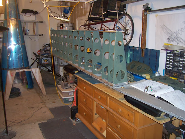
Finally nutplates were added here and there to attach the stall warning switch and electrical plug.  Two main ribs get doublers attached and the flaperon hinge brackets are match drilled to be riveted on later.  Then there was priming to do.  I lost count of the number of five-dollar rattle cans I went through as I put multiple coats of self-etching primer on each rib for uniform coverage, while simultaneously wondering whether I'm wasting time and money trying to protect al-clad aluminum, which is already corrosion resistant, especially in a low-humidity area like Sacramento.  Eventually (as in, it took me a couple months) the ribs were prepped and ready to rivet.  Once again neighbor Ken helped me take the left main spar down from an overhead rack to the work table so I could start turning it into an airplane wing.  They're light enough for one person, but as Dave G noted, in tight quarters the main spars can be 15½ feet of mayhem if you're not careful.  The picture below shows the four stacks of wing ribs ready to go: L & R main ribs and L & R nose ribs.  Interestingly, it's mostly right ribs that go on the left wing, and left ribs that go on the right wing.  More Van's humor, that.


With the ribs now prepped I could finally start attaching main ribs to the left main wing spars - visible progress just in time for the arrival of holiday guests. 
Merry Christmas everyone!


Thursday, October 17, 2013

Fluting the ribs

Over 3 months since I last posted.   Not a very good blog is it?  I pretty much took the summer off from working on the plane so I don't have that much to report. It was just too hot to hang out in the airplane factory for very long.  Project momentum, which never really got going after the wing kit arrived in April, just kind of went phftt.  A very wet phftt.  Lest Mr. B. think I'd given up (and demand all his tools back) I thought I'd post a brief update and come back later when I have pictures of actual completed airplane parts to show.  Now that the lame-o excuses are out of the way, Page 15, Step 1 tells us to "flute" the ribs. What? Don't believe me? Says so right here:

I'm more of an amature air-guitarist myself, but fortunately there is a future flute virtuoso residing in the household that I feed and clothe for just these very occasions.  Figuring it was about time she earned her keep around here, I asked the future co-pilot to "flute" the ribs for me.  Based on the undertone of the composition she selected, I think she might be having reservations whether dear 'ol dad knows what the heck he's doing (and perhaps whether he's lost his marbles).  Have a listen and decide for yourself:

 
 Honestly, I don't know how other RV builders do it without having one of these around!

Tuesday, July 2, 2013

Flaperon Hinge Brackets

On page 14-2, steps 3 & 4 we rivet doubler plates onto the inboard end of the stub spars.  Eight of the rivets are of the AN470 "mushroom" type and the three at the end are the tiny flush rivets.  Think of the ends as "Tab A" that slip into "Slot A" in the airplane fuselage near the wing's inboard leading edge.  To make the "Tab A" rivets flush on both sides, we countersink the three holes with the 100º countersink bit on both sides before squeezing the rivet.  The shop side of the rivet expands to fill the countersink.  The plans say to use the AN426AD3-3 rivets but I read in the builder blogs that those were a little short and that using the 3-3.5 rivets worked slightly better.  So I used those instead, but not before sanding a millimeter or so off the rivet length.  The main thing is that the "Tab A" rivets be flush on both sides and that's how they turned out.

In steps 5 & 6 we rivet together four hinge brackets for the flaperons (two per side) using the mushroom rivets.  Analogous to the stabilator (horizontal stabilizer & elevator), flaperons are a combination of wing flaps and ailerons.  Not sure who first thought up the idea, but it's quite clever.  Flaps help slow the plane down and ailerons are used to bank right or left.  Flaperons do both, and fewer moving parts means a faster build.  The Marine Corps' V-22 Osprey uses flaperons, but of course it transitions into helicopter mode to slow down and land.

The flaperon hinge brackets' holes are pre-drilled so all I have to do is deburr the holes and push a rivet through two halves of each bracket and squeeze it with a rivet squeezer.  There’s a possibility of warping the bracket during rivet squeezing so the plans say to install the rivets in a random pattern, whatever that means.  Although not very efficient, earlier I found a method that seems to work well in this situation:  Just give each rivet a half-squeeze –  enough to squish the rivet just a little, and then move onto the next.  Once all eight rivets are in, give ‘em a three-quarters squeeze, and then finish it off with a full final squeeze on each rivet.  That seems to result in good uniformity and kept the brackets nice and straight.  The technique seemed to work pretty well, which, as you know by now, meant that I was overdue for screwing something up.  One of the rivet holes was just a little too small, and instead of reaming it to the correct size, I tried to brute-force in a rivet and ended up with a deformed and stuck rivet that would neither go all the way in or come back out.  Then, in trying to get the rivet out using various techniques, I marred one of the two pieces that make up the bracket.  Just cosmetic of course, but the part will be visible on the finished wing and the scratches (plus a small dent - don't ask) would not be something that could be hidden under a coat of paint or smoothed out.  Besides, a replacement was only six bucks plus a couple bucks for shipping, so I went ahead and ordered it.  I knew that if I didn't I would cringe inside anytime someone inspected the flaperon hinges.

So with a replacement bracket half quickly mailed priority post from Oregon I braved the punishing heat of the garage for half an hour or so last night to finish the fourth and final flaperon hinge bracket thus completing Step 6.  Didn't take long but the heat and humidity was exhausting so I'm going to avoid doing that again.

With temperature forcasts in the 110-degree range this week (and the garage/airplane factory often several degrees above that) any further work in Section 14 is going to have to be moved indoors until, oh, September.  The CFO should like that.  She always appreciates it when airplane tools and parts are scattered all over her kitchen counter.

Friday, June 21, 2013

Chapter Two - Wings

I know. It's been a while since I last posted.  But I'm back.  Since the wing kit arrived ten weeks ago I completed Section 13 (Spar Assembly) and Steps 1 and 2 of Section 14 (Sub Spar).  I'll just catch up by hitting the highlights.  Step zero, of course, was to inventory the shipment, organize parts, and demolish the crates (I saved one of the crate lids).  But instead of demolishing the square crate, I thought perhaps someone in the neighborhood could use it for a backyard sandbox for a toddler.  So one morning I set the empty crate out at the end of the driveway with a FREE sign on it and did some driveway sweeping.  A minute later the driver of a landscaping truck turned down my street, drove by, stopped, backed up, and asked if he have it.  I said "Sure! Take it!" and helped him load it in the back of his pickup.  Turns out his dog just had a litter and with appropriate lining the sturdy crate was perfect for corralling the pups while letting mom hop in and out to attend to business.  Win-win!


So I started doing the inventory and at first thought I only received wing ribs for the left side, since all the ribs were tagged "L".  For a while I thought perhaps I received ribs for two left wings and that some other builder somewhere received ribs for two right wings (which would have meant having extras in case I bungle a rib - not necessarily a bad thing).  Closer examination, however, revealed that L & R ribs were stacked as pairs and that the "R" rib labels were simply hidden by the "L" ribs.     
The first thing in Section 13 is to separate the rib clips with the band saw (snips work too) and debur and remove the connecting material with a scotchbrite wheel.  Then I lined up a bunch of small nails on the salvaged crate lid to hang the clips to give 'em a coat or two of self-etching o.d. primer "just because".
Next step was to drill and tap 3/8" x 16 tpi holes in both ends of the AEX (I think it stands for Aluminum EXtrusion) bracket that came pre-riveted onto each wing spar with the over-sized rivets.  No drama with broken tap handles this time.
One of newly threaded holes will be for an eyelet bolt to serve as a wing tie-down point.  I'm not sure yet what the hole on the other side of the bracket is for.  Pilots use tie-downs 'cause you don't want your plane taking off without you when a bit of wind comes along.  At AirVenture last year either a gusty wind or a windy gust lifted a WWI replica plane up and on top of another plane parked at the event (Oshkosh follies).  Another time as a student pilot I watched the rotor wash from a big Skycrane helicopter lift a plane not tied down at the Madera airport off its gear and into the plane parked next to it (Madera follies).

With drilling and tapping the AEX brackets completed, on Page 13-03 we
1.  Cleco the rib clips to the wing spars;
2.  Cleco the outboard attach clips to the wing spars;
3.  Rivet the outboard attach clips;
4.  Rivet all the rib clips; and
5.  Rivet all the factory-installed rib clips as marked in the plans (mostly LP4-3's, and a few of the slightly longer LP4-4 blind rivets). 

Once again the pre-punched rivet holes are close to the 90-degree angle on the rib clips making it impossible to get the pop-rivet tool barrel square onto the rivet, so again we used the little wedges to pop the mandrel from the rivets at an angle.  In case you're wondering what the circle thingy is in the picture, that would be one of the two wing spar bushings.  Here's a picture of what it looks like when it's removed.  Due to thermal expansion of aluminum I can remove and insert these when it's hot, but not when it's cold.                            
                                            Eventually large pins will go through the brass bushings to transfer up to several thousand pounds of load (or lift) from the wings to the fuselage (and vice-versa) depending on g's, so the spar bushings and pins are definitely of the DO NOT REMOVE DURING FLIGHT variety, not that you could. 

Counting up the used mandrels from all the pop-riveting indicates that about 150 rivets were installed in steps 3, 4 & 5 to fasten 20 rib clips, the outboard end clips, and the rib clips partially installed at the factory (they did the big outside rivets but not the small inner ones).  Just 11,000 more to go, give or take, but who's counting. 
Wrapping up Section 13 I hung the spars up out of the way with the assistance of a neighbor across the street.  I'm amazed at the engineering on these things - relatively light yet very strong.

Moving on to Page 14-02 Step 1 we simply cleco on the inboard doubler plate to the stub spar which becomes a good place to apply a clamp to keep the piece stable on the work bench while drilling countersinks in Step 2. 

In Step 2 we use a countersink bit to countersink holes in the stub-spar.  There's 42 holes on each side (as all good science-fiction geeks know, the number 42 is also the Answer to the Ultimate Question of Life, The Universe, and Everything).  Both sides times two wings gives 168 countersinks.  That took a couple of work sessions and gave my drill battery a good workout.  Until now I've checked each of my countersinks with a flush rivet to test for "flush-ness".  In this case however there's no rivet to test with.  Later on in Section 17 wing skins will be attached directly to the stub spar with CS4-4 rivets that will form a very shallow dimple to make the wing's inboard leading edge as smooth and round as practical.  So to get the depths right Vans has us drill a ¼-inch hole in a piece of scrap aluminum to use as a depth guide.  When the countersink is exactly ¼-inch in diameter the depth is correct.  Just be sure you check the guide hole with your micrometer before you start.  My first guide hole was too big so I had to go down one bit size (15/64ths).  The second hole was slightly oval-ish, but the "skinny" side of the oval was exactly 0.25 so I marked and used that as my guide.  In the end a few of my 168 countersinks came out a teeny-tiny bit oval-shaped due to the drill not being perfectly square-on, but I think they're okay.  Good news is that the guide worked just as well as a rivet would have for checking depth and I don't think I under- or over-countersinked any of the holes.

Tuesday, April 9, 2013

Wings Kit Arrives

The long-awaited shipment from Oregon arrived today.

Sturdy and damage-free crates were offloaded and moved into the airplane factory.  See the red dollar signs on the crate?  Quite accurate.  So a trusty security guard was appointed to keep an eye on it.


And the workspace cleared off.  It's amazing how much stuff a horizontal surface collects when you're not paying attention to it.

And now it's time to get to work!  Hooyah!

Thursday, February 7, 2013

Finished with empennage (for now)

I sent in the order form and check to Van's Aircraft for the wing and lighting kits, which ups the cost tally to ten grand.  As they say, in for a pence, in for a pound.  I can understand why the wing kit costs so much ($5,700) with the main spars and all, but I'm not sure why the optional lighting kit is $1,350 and wonder if the word "optional" has anything to do with it.  I guess I'll find out.  Since their web site says it takes eight weeks to fill and ship a wing kit order, I probably should have sent the order sooner.  Now I'm fresh out of things to work on.  The delay was because I'm relying on tax refunds to pay for it, and it took a while to convince the worried CFO that I would get our tax returns done early this year instead of waiting 'til the last minute as usual.  Her skepticism isn't misplaced doing taxes is my 973rd favorite thing to do, right after "get root canal" and "bang head on brick wall".  It takes hours to go through the TurboTax interviews that end up being a waste of time because the total expenses don't exceed some percent AGI limitation.  Then when it's done I always feel like there's some additional expense I should've listed on Schedule A or E or whatever, and that everyone else is interpreting what's deductible and what's not more liberally than I am.  IMHO the tax system shouldn't force 30 million otherwise honest long-form taxpayers to confront these ethical dilemmas.  Or hold on to so doggone many friggin' receipts.  Unlike Congress, not everyone can afford an accountant, so make it simple.  Stop using the IRS as an instrument for social change and get rid of all deductions, credits, loopholes, and incentives.  And lower the tax rates to compensate.  JFK lowered the tax rates in 1964 and Reagan did it in 1984 and both times tax revenue doubled within a couple of years and achieved better tax compliance.

Enough ranting about government and taxes.  There were a couple things left to do on the empennage that didn't require assembling the tailcone, stabilator, v-stab, and rudder.  Build plans pages 11-6, -7 & -8 has us make the aft servo tray and AST pushrod assembly.  Those parts connect the trim servo to the trim tab.  For those who don't know, a servo is a small electric motor that moves a connecting rod forwards and backwards. The trim tab is a control surface that pushes against the slipstream in flight.  Trim is used so the pilot can fly hands off instead of always pulling back on the control stick (to climb) or pushing forward (not climb).   It's also used by the autopilot to adjust airplane pitch attitude.

The hardest part was crimping Micro-fit pins onto the wires coming out of the the servo motor.  The 26 gauge wires are small and the pins are too.  Seriously.  Check out the picture.  The flanges on the pins are only a couple millimeters wide.  You need good eyes, a magnifying glass, and the skill of a surgeon to crimp the Micro-fit pin onto each wire using a special crimping tool that costs $324 bucks.  Fortunately Fry's has one that's used for crimping 30-gauge d-sub pins similar to Micro-fit pins that's nearly as good and only costs $17.  It was a tough decision but I chose that one instead.


Not being particularly gifted in manual dexterity the crimps were less than perfect, but they're tight, they conduct electricity, and the pins won't slip off the wires (or vice-versa).  I hope.  Once the pins are crimped onto the wires they're inserted and locked into a mini-Molex plug that will plug into the wiring harness.  Assembling the rest of the pushrod assembly was fairly easy, if a bit time-consuming.  Here's a picture of the finished pushrod assembly with the servo:

 At this point the push rod assembly is supposed to be fitted onto the tailcone bulkhead and trim tab and adjusted.  Since I'm not bolting those things together at this time the pushrod goes back into the drawer.  It won't be installed until after the wings and fuselage are done.  Couple of years maybe.  This is a VSB, remember?   And that wraps up everything I can do in Section 11.
Moving on to Section 12, Vans has us trim the bottom and rear of a fiberglass vertical stabilizer tip.  Mister B's belt sander was especially well suited for that.  The bottom of the v-stab tip is flat, and the belt sander is flat, so trimming was easy, if somewhat smelly.  This was definitely a breezy-day outdoor job.  You don't need fiberglass dust in your work area.
Once trimmed I test fit the tip on the v-stab and sanded a little more for a perfect fit.  Pretty easy with the belt sander.  Then I wrapped sandpaper around a paint spray can to trim the curve at the back indicated by a scribe line.  Once the fit is perfect rivet holes are match-drilled, cleco'd, and the tips are riveted on.  I'll probably do a little more fit sanding with the rudder on to get 1/8" clearance between the v-stab tip and the rudder tip through the full range of rudder travel.  It shouldn't take long.

It was the same procedure for the rudder tip.  This time, instead of doing it on the driveway, I set up a work table.  Much better for my achy back.

For the rudder tip it was a much tighter fit onto the rudder and at first it didn't want to go in.  By sanding an angled bevel on the bottom of the tip I was able to to fit it on.

With the tips now riveted on, the v-stab and rudder were moved back to an out-of-the-way corner in the family room.  And that's all I can do for now until the wing kit gets here in six or seven weeks.

Time to work on taxes.

Tuesday, January 29, 2013

Six month review

Let's review, shall we?  In the last six or seven months I built the vertical stabilizer (aka "fin"), the rudder, the horizontal stabilator, the vertical trim tab, and the tail cone.  Now in Section 11 of the build plans we're supposed to put all those things together to check fit, control surface travel, and the like.  While it would be pretty cool to start assembling the plane (instead of just its parts), it would also take up a lot more space with everything bolted together.  Space I'm gonna need to build the wings.  So I'm gonna skip that part of Section 11 and come back to it in a couple of years when the wings and fuselage are done.  The kits are so well designed and manufactured I'm not worried about the fit or travel.  I'm also told it's easier to build the fuze without the tailcone on.  The wings, when finished, will get hung from the garage ceiling out of the way until the plane is ready to fly.  So what's next besides sending a really fat check to Vans for the wings and lighting kits?  Well, there's still plenty to do, so stay tuned.

Saturday, January 19, 2013

Finishing the Tailcone

I borrowed some clecos from Gawdl Muhrt, the Guy at work [who] doesn't let Me use his rivet tool, which gave me enough to put the top skin on the tail cone and secure it.
There's one more item to work on before I can start riveting the tailcone, and that's the rib for attaching to the  forward skin on the vertical stabilizer.  The rib has eight nut plates that need to be dimpled and riveted on.  The tiny #3 rivets were actually pretty easy to squeeze single-handed, as you can see:
Just push the handle down 16 times (twice per nutplate) and it's done.

The rib is cleco'd and riveted on top of the top skin near the back.  It'll be used to attach the forward skin on the V-stab.

With that out of the way it was finally time to start riveting the rest of the tailcone skins together.  It took a while using the manual pop-rivet gun.  I tried to borrow a pneumatic pop-rivet gun from the guy at work to speed things up but Gawdl kept muttering something about me breaking it before he had a chance to do his project.  He probably heard about me breaking Mike's tap handle.  I dunno.  It's like he doesn't trust me or something.  So I used the manual one that came with all the other tools Mr. B loaned me.  Rivet after rivet, row after row, hand muscles getting sorer and sorer until... I broke it.  The wire spring that spreads the handles apart sheared from metal fatigue.  Don't worry Mr. B;  I picked up a new pop-rivet tool at Home Despot:

Which works very well.  It really doesn't take that much longer compared to a pneumatic one.  Three good squeezes and pop!  The rivet is set.  Actually takes me longer to get the rivet set up -- sometimes it just doesn't want to slip into the hole right away and needs a little poking, prodding and persuading with an awl.  Here I'm finishing up the last few rivets:

Some of the rivets in the area where the front of the V-stab attaches are a bit hard to get to.  You can see here about 1/4 inch gap between the rivet mandrel and the forward V-stab attach bracket -- not enough room to get the barrel of the rivet tool over the mandrel.  So I did like before and used the little wedges we fabricated way back in step 1 to pop the mandrel off at an angle.

I counted up all the used leftover rivet mandrels before throwing 'em away as a way to gage progress.  When the 12,500 rivets I bought are gone, the plane is done.  Completing the tailcone required 1,148 rivets, give or take, and countless times moving clecos around.  Still no Popeye arms though, darn it.

And that wraps up Section 10.  I moved the tailcone out of the way to organize the shop area in anticipation of starting on the wings later this year (after tax returns are done - per the CFO's insistence.  I think she's trying to motivate me to not wait until April 14th as usual).  I think it looks good in the spot formally occupied by the Christmas tree that I finally took down last week.  Reminds me of the newfangled artificial tree at the tree lot in A Charlie Brown Christmas that sounded like an old oil drum.       

Yep.  Just needs a little decoration is all.

Tuesday, January 8, 2013

Upper Tailcone Skins

Once I got the trim motor wiring, static port tubing, and pull strings for the stabilator control cables in I added on the upper left side skin...

... and then the upper right side skin: 

And I am out of clecos.  See how spaced apart they are?  Not good.  Fortunately I was able to borrow more from Gawdl Muhrt, another guy that I work with, who picked up a bunch at the same time as me (at half-price due to factory blemishes!) to restore an old Airstream trailer.

In the next step we cut the rudder cable(s) bushing bracket(s) with the bandsaw
and debur with the scotchbrite wheel.  The brackets get riveted inside the upper skins at the very back near the bulkhead.  Snap-in bushing-grommets are inserted and strings are run from the back to the front to pull the rudder cables through later.  Now it's time to start riveting the skins together.  If only Gawdl would let me use his pneumatic pop-rivet gun...

Monday, January 7, 2013

Wiring and Things

There's a few items to take care of before the upper left and right skins are attached.  As noted previously, the wiring harness for the AST trim tab motor needs to be routed down the left side of the tailcone.  In addition to trimming the airplane, the AST motor will also used by the autopilot to control pitch attitude.  Pretty cool, eh?  None of the Cessnas I've ever flown had any of that fancy schmancy autopilot stuff.  Since one end of the harness already has a small plug for the wires (and since the plug does not fit through the grommet on the rear bulkhead), the decision is made for you which end is which:  You pull the wire forward from behind the rear bulkhead, leaving six inches (and the plug) behind the bulkhead.  The wire harness is routed down the left side J channel and secured with zip ties.  The forward zip ties are left loose until the static tubes are installed.

For the two static ports, first we rivet in the right side static port, which is just like a regular pop-rivet but with a big head on it.

And then the left side.  After the static ports are pop-riveted on, the mandrels inside the static port-rivets are driven out with a small punch and hammer.  I followed other builders' advice and took a block of wood, drilled a hole in it and had my assistant, the lovely but unnamed CFO, hold it against the inside skin so I could knock the leftover mandrel piece out the other side without denting the skin.  Both punches I have were too big to fit in the hole so I just used an old mandrel and it worked fine.


After the mandrels are driven out I installed the static port tubing.  The clear tubing appears to be the same stuff you'd find in a fish aquarium.

Tubing for both sides is routed up the large frame hoop and connected in the middle with a T fitting.  It's a bit different from earlier RV-12's, which had the tube from the right side port go all the way over to the left side port.  The difference is related to a recent change in the design of the avionics system.  The static port(s) tubing, both 1/8-inch the and 1/4-inch, are then secured with zip ties as shown:

Not sure if it's needed, but RTV silicone was used to seal the tubing to the static ports.  I had some left over from when I swapped the water pump in my truck a few years ago.  The stuff's just as messy now as it was then.

While I was doing this, something about the routing of the wiring harness at the rear bulkhead kept nagging at me.  I knew it would be difficult to inspect if the edge of the J-channel ever chafed it's way through the harness and shorted out the wiring.  And since I had already cinched the zip ties, it would have been a fair amount of work to put protective shrink-wrap over that section, which I didn't have anyway.  A delay and a step backwards, if you will.

So I came up with a alternative plan involving three pieces of electrical tape:

First I pulled the harness out of the way and wrapped the small piece of tape over the edge:

 And then wrapped two more pieces of electrical tape over the first one like so:

It seemed like a good idea to do it for the front as well:

The problem is that electrical tape just isn't all that sticky and could come off on its own one day.  As long as it stays on though, it'll protect the harness from chafing at the ends of the J channel.  I'll just add that the sheath on the harness seems to be pretty chafe-resistant and the wires inside it are sheathed in Teflon.  Once the harness is connected to whatever it is that it gets connected to, I should be able to add in just enough slack so that it barely touches the fore and aft edge(s) of the J- channel.