Natomas Follies

VSB - very slow build

Monday, January 7, 2013

Wiring and Things

There's a few items to take care of before the upper left and right skins are attached.  As noted previously, the wiring harness for the AST trim tab motor needs to be routed down the left side of the tailcone.  In addition to trimming the airplane, the AST motor will also used by the autopilot to control pitch attitude.  Pretty cool, eh?  None of the Cessnas I've ever flown had any of that fancy schmancy autopilot stuff.  Since one end of the harness already has a small plug for the wires (and since the plug does not fit through the grommet on the rear bulkhead), the decision is made for you which end is which:  You pull the wire forward from behind the rear bulkhead, leaving six inches (and the plug) behind the bulkhead.  The wire harness is routed down the left side J channel and secured with zip ties.  The forward zip ties are left loose until the static tubes are installed.

For the two static ports, first we rivet in the right side static port, which is just like a regular pop-rivet but with a big head on it.

And then the left side.  After the static ports are pop-riveted on, the mandrels inside the static port-rivets are driven out with a small punch and hammer.  I followed other builders' advice and took a block of wood, drilled a hole in it and had my assistant, the lovely but unnamed CFO, hold it against the inside skin so I could knock the leftover mandrel piece out the other side without denting the skin.  Both punches I have were too big to fit in the hole so I just used an old mandrel and it worked fine.


After the mandrels are driven out I installed the static port tubing.  The clear tubing appears to be the same stuff you'd find in a fish aquarium.

Tubing for both sides is routed up the large frame hoop and connected in the middle with a T fitting.  It's a bit different from earlier RV-12's, which had the tube from the right side port go all the way over to the left side port.  The difference is related to a recent change in the design of the avionics system.  The static port(s) tubing, both 1/8-inch the and 1/4-inch, are then secured with zip ties as shown:

Not sure if it's needed, but RTV silicone was used to seal the tubing to the static ports.  I had some left over from when I swapped the water pump in my truck a few years ago.  The stuff's just as messy now as it was then.

While I was doing this, something about the routing of the wiring harness at the rear bulkhead kept nagging at me.  I knew it would be difficult to inspect if the edge of the J-channel ever chafed it's way through the harness and shorted out the wiring.  And since I had already cinched the zip ties, it would have been a fair amount of work to put protective shrink-wrap over that section, which I didn't have anyway.  A delay and a step backwards, if you will.

So I came up with a alternative plan involving three pieces of electrical tape:

First I pulled the harness out of the way and wrapped the small piece of tape over the edge:

 And then wrapped two more pieces of electrical tape over the first one like so:

It seemed like a good idea to do it for the front as well:

The problem is that electrical tape just isn't all that sticky and could come off on its own one day.  As long as it stays on though, it'll protect the harness from chafing at the ends of the J channel.  I'll just add that the sheath on the harness seems to be pretty chafe-resistant and the wires inside it are sheathed in Teflon.  Once the harness is connected to whatever it is that it gets connected to, I should be able to add in just enough slack so that it barely touches the fore and aft edge(s) of the J- channel.

Tuesday, January 1, 2013

Tailcone Bottom

I knew the day was coming when I would no longer be able to make do with the number of clecos I have available, and so it has.  Nevertheless I was able to get a lot done over Christmas and New Years.  In fact, this picture makes it look like I have lots of clecos:

And so there is, when all you're doing is fastening the two bottom skins to the frames.  Add the next couple of skins, however, and the ranks start to thin:

So I had to spend a lot of time moving clecos around to optimize spacing and persuade each hole to line up.  The holes in the skins are precision-punched at the factory and I resolved that I wasn't going to do any match drilling to make the rivets fit if I could help it.  Eventually I managed to get each of the three bottom seams laid down nice and flat, except for this one area on the port side:

Don't know why I couldn't get that section of bottom skin to cooperate.  Thinking that maybe it had something to do with the way the clecos were advanced in various directions, I removed most of the clecos forward of the middle frame hoop and started over. Employing various strategies (including a full-on cleco assault) I was able to get the skin to lie down (lay down?  I think I missed that day in English class) a little better, but not much:

Having done all I could do it was time to start riveting.  That took a long time too, since I don't yet have a pneumatic pop-rivet puller to use.  Generally started in the center and worked my way out, repositioning the freed-up clecos as I went.  Once the bottom rivets were in the "bump" went down some, but I can still just get my fingernail under the edge.  The other 300 inches of seams came out nice and tight, but that little bump, well, I guess I'll just live with it.  Hopefully whoever looks underneath the plane to scrutinize the rivet lines won't notice.  I can just hear it now: "Have a little trouble with the edge-breaker, didja?"  A bit blurry, but here's the same area after riveting the four bottom skins together:

And here's the rest of the bottom with rivets:

Now we turn the whole thing over to add the left and right side skins.  It's not hard 'cause it doesn't weigh much.  Riveting the bottom freed up a lot of clecos, which is good 'cause we're gonna need 'em.  Here it is turned right side up: 

Before we put on the side skins, however, we fasten in the aft bulkhead that we spent so much time on.  That required a lot of manual persuasion and I'm sad to say that there were more than a few scratches added to the skins where the aft bulkhead went in.  The aluminum alloy skins have a super-thin layer of pure aluminum that serves to protect the alloy from corrosion, so you want to avoid deep scratches if you can.  Here's the aft bulkhead installed on the bottom skins:

The vertical stabilizer and horizontal stabilator will attach here.  The skid plate protrudes out the bottom just a little bit, about 1/8 inch or so.  Once the bulkhead is fastened in the side skins are cleco'd on:

There's just three more skins left, and once they're on it will be really hard to get back in there.  So it was time to peel off the blue protective film while I still had easy access.  Other items that are easy to do now (and don't require any clecos) are:  Route the wires for the AST servo (electric trim tab), add static-air ports and tubing for the avionics, and run kite strings for fishing the rudder and stabilator control cables through later.

Monday, December 24, 2012

Finishing rear bulkhead assembly

All but four of the 100-plus rivets needed to complete the rear bulkhead assembly can be squeezed using one of the two "C" yokes that came with the Cleaveland Main Squeeze rivet squeezer (a dozen or so are of the "pop"-rivet variety).  So I saved those for last, which, in retrospect, was kinda dumb.  Shoulda done 'em first.  The yokes have about a two-inch reach.  To get those last four rivets squeezed requires a yoke with a three-inch reach, which I don't have.  That means it was time to learn how to use a pneumatic rivet hammer and bucking bar.

Remember back in July I borrowed my neighbor's air compressor?  Well, six months later I finally fired it up and tested out the rivet hammer.  To my relief, both worked perfectly.  Here's what those items are:


By this time the rear bulkhead assembly had quite a number of hours invested in it and I didn't want to mess it up when it was so close to being finished so I asked the owner of nearly all of the tools that I've been using, Mr. B, for his assistance bucking those four rivets.  Mr. B was a great sport and came over to help.

First thing we did is select the right bucking bar out of the four or five that came with his rivet gun.  But even the one with the small end on it was slightly too large for the narrow space available to work with, now that all of the other "easy" rivets were in.  So Mr. B took a little bit off the corners of the bucking bar with the bench grinder.

And it worked!  Then Mr. B held the bucking bar and bulkhead steady and I "shot" the rivets with the rivet gun.  Due to my lack of experience (no dry run practice for me, thank you very much) a couple of rivets had to be drilled out, but fortunately we noticed that the top of the rivet wasn't sitting flush before getting too far along.  All part of the learning curve.  A bit later all of the rivets on the rear bulkhead were done.  Thank you Mr. B!


Before we finally get to the actual building of the tail cone skins, there's one last chance to test fit the bulkhead to the stabilator.  See those bearings?  The AN4 stabilator hinge bolts go through those with a washer on each side of each bearing.  AN4 hinge bolts are 4/16ths diameter (1/4" for the fractionally-challenged), which seems a bit wimpy.  But if you do the math you get a bolt shear plane of just under ¼ x ¼ x ¼ π = .05 square inches.  Multiply that by the shear strength of the bolts, about 100,000 psi, and you get almost 5,000 lbs of force required to shear the bolt.  Multiply that times four possible shear planes (two per bearing), and you can deduce that other parts would fail before those bolts will.

Vans has you choose whether to use a thick washer or a thin washer on each side of each bearing, as long as it's symmetrical.  So the choices are:  four thin washers, four thick washers, or two thin and two thick.  You determine which ones give the best fit in the stabilator brackets.  A good fit is snug (no lateral movement between the bulkhead and the stabilator), but not too snug.  Once you select the right washer combo they're super-glued in place onto the stabilator brackets.  That's 'cause, unless you have very small slender hands, those bolts and washers are difficult to place and even harder once the tailcone is assembled.  Having my eight year-old daughter help out really came in handy.  In my case the magic combination is two thin washers and two thick washers.  Perfect fit.  Just hope they don't fall off.

Note for RV builders who are married:  You may want to keep the fact that you're using super glue on the airplane to yourself.  Even though you're just using it to temporarily hold a couple washers in place, it doesn't help the confidence-building with your spouse, if you catch my drift.  Trust me on this one.

Merry Christmas everyone!
 

Sunday, December 23, 2012

Skidplate Fabrication Part 2

I went a little bit out of order.  You're supposed to tap out the hole first, and then put it on the rear bulk head to drill the rivet holes in the skid plate.  But since I didn't have a tap handy, I went ahead and did the rivet holes drilling first.  In this case it didn't make any difference.  Next day I borrowed a 3/8" x 16 tpi tap and handle from a guy at work known for having a nice tool collection, drilled out the hole and started threading the hole with the tap.

As you can see, it gets harder as you go, until...

Uh-oh.  Broke the jaws on my friend's tap handle.  What are my options?

Vice grips can do a lot of things, but turning a tap isn't one of them (seemed worth a shot though).

This doesn't work either:

So I went to Home Depot to get a new beefier handle.  I'm sure I'll use it again sometime.
So with lots of turning, unturning (to clear out chips), and turning again, plus a few drops of bike chain oil, I eventually ended up with a nicely threaded one-inch hole in the bottom of the skid plate to screw the rear tie down eye bolt into.  Following day I returned the tap and asked my co-worker if he wanted me to replace the broken tap handle and he said he had extras and not to bother.  We'll see if he lets me borrow any more of his tools in the future.

With the skidplate fabrication done, we're ready to rivet together the bulkhead assembly, and here's what that looks like (well one side anyway):
Note that all 95 (or so) rivets are done except the two on the left and two on the right.  There's no way that the rivet squeezer I have with its two-inch "C" yoke was going to reach those two rivet holes, what with the "ears" for the main stabilator bearings on the reverse side being in the way.  I've mastered (sort of) the hand rivet squeezer.  Now it's time to learn to use the pneumatic rivet hammer.

Friday, December 21, 2012

Skidplate Fabrication Part 1

Page 10-3 has us fabricating a skid plate by taking a section of extruded aluminum, cutting several pieces off of the extrusion, and threading the center hole with a 3/8" tap.  Funny that they would call it a skid plate, since the part will never touch the ground.  But it will provide a place to screw in an eyelet bolt to be used as a rear tie-down point.  I suppose if you were to really over-rotate on landing or take off the eyelet bolt could scrape the runway, but airplanes aren't normally flown that way (sure would wake you up if you did).  Still, it's good to have because eyelet bolts are cheap and easy to replace, whereas runway rash on the rear bottom skins, well, I don't even want to think about what a PITA how difficult that would be to repair.

 Here's the [mostly] unmolested piece with a cut mark on it:

And here it is after a little band saw surgery:
The next couple steps use the drill press, band saw (again), and scotchbrite wheel on the bench grinder to remove additional material at the bottom (right), and to grind out a notch in the side, as shown:
A thin aluminum template is used to locate the notch and drill the first two of 16 rivet holes.  Here's an important builder tip for drilling those first two rivet holes:  After drilling the first rivet hole, cleco the template to the skid plate using that hole.  Guess what happens if you don't.  That's right, your second hole may end up in the wrong location.  Using the magic of Photoshop <not>, here's what that would look like ('cause I would never do anything that stupid):
So remember, cleco the template with that first hole.  You might even consider drilling just one of those two rivet holes now, and the rest when the plate is on the bulkhead.  Cleco each as you go.  That will allow you to precisely center the bottom part of the skid plate (with the threaded hole) between the doubler plate flanges on the bottom of the bulkhead.  Be sure the notch position is okay before you start drilling.

Tuesday, December 11, 2012

Back in the Saddle

I know.  It's been over a month since I last posted.  Truth is, I just haven't worked that much on the plane.  Lots of yard work and things like that have gotten done on the weekends (with body aches to prove it), but for some reason my enthusiasm for evening work on the plane has wained a bit with the shorter days, despite taking a day or two off to work on it.  I need to get on the ball though.  There'll probably be a scheduled price increase in February on the various kits that Van's sells and I'll want to have my order placed for the RV-12 wing kit before then.  Because of workspace issues I'll also want to have the tailcone finished and stowed away before the big crate full of airplane wing parts arrives at my door.

So what have I done in the last month?  Well, I
 * removed the blue plastic protecting the skins along all the rivet lines,
 * deburred all the rivet holes and edges,
 * bent the edges on the tailcone skins per the plans (not hard, once someone shows you how),
 * fluted the frames to straighten the rivet hole lines, and
 * fastened together the tailcone frame hoops shown in picture.
The large and medium hoops are easy - a few pop rivets and you're done.  The small hoop, the one that goes at the very aft of the tail cone, required the assistance of my neighbor Ken because there's a doubler plate and six-inch angle fastened with #4 rivets that need to be squeezed, and the pieces are too light to secure firmly while operating the rivet squeezer, which is also awkward to use (for me anyway).  In return I promised to help Ken clean out his second-story rain gutters this weekend.

As you can see, I did manage to mess up the first rivet (bottom row left) by oversqueezing it, I think.  Somehow there ended up being a small gap between the doubler plate and the frame after I squeezed the rivet.  So I drilled it out and, since the hole is now enlarged, ordered some #5 rivets from Aircraft Spruce to use in that hole.  They should arrive any day now.  The other 17 rivets went in pretty well because I took my own earlier advice and only gave each rivet a half-squeeze until all 17 were in, then went back and re-squeezed down to spec.  It also helped a lot having Ken hold the frame steady while I manned the rivet squeezer.  With the exception of the first bottom rivet (soon to be fixed), I'm satisfied with it.
Picture of tail cone frame frame

December 18 update:  The # 5 replacement rivets came in the mail so I could finish the final rivet in the small bulkhead hoop.  You're not supposed to use a Cleaveland Main Squeeze rivet squeezer on 5/32" rivets but I used it anyway and didn't break anything.  Here's the # 5 "oops" rivet next to seventeen # 4s:
It should be okay.  It's deep in the tailcone and faces aft, so no-one will see it anyway.

Saturday, November 3, 2012

You Meet the Nicest People

Step 1 of Section 10 has us "break" the edges on six 8' tailcone skins.   By "break" they mean bend the long edges of the skins a few degrees so that the overlapping edge is flat and snug when the skin is riveted (the clamping pressure of a rivet can cause the edge to lift a little bit).   Due to the geometry of the tailcone (radius is smaller at the back end than the front end) the bend, or "break", increases as you move down the narrow end(s) of the skin(s).  Fortunately there's a handy tool for breaking edges (shown in the picture) that I borrowed from the guy at work.  Apparently it's easy to use once you learn how.  Problem is I don't know how to use it.  Seriously.  Clueless.  Never seen it done before.  The owner of the tool never used it either.  So I put a message out to the Sacramento RVators group to ask for help. 
Right away the group's founder, president, secretary, treasurer, and newsletter editor, Ed Martinson, put me in contact with Kerry Richburg, a retired fellow who flies a beautiful RV-9A he built at Sacramento Executive airport.  Kerry took time out of his morning (he was prepping to fly to Monterey) to introduce me to the edge tool and a few other tools that I'll be needing down the road, including a tube bender and fuel line flaring tool.  The SacRVators group loans them out like a library book so that RV builders don't have to shell out dough for an expensive tool they may only use a few times.  Here's a picture of Kerry and his -9A:
 
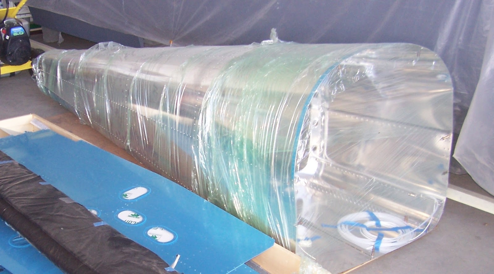
Kerry demonstrated proper technique for breaking an edge and gave me some scrap aluminum to practice with (it's not like you can just pick up 2024-T3 0.020" aluminum at Home Depot, and none came with the kit).  He also passed along info about a flying club called DGA (Damn Good Association) located at the other end of the airport.  The club's hangar is open weekends and anyone can drop by and take the nickel tour of some of the club's 10 different airplanes.  At any given time the club is always rebuilding some vintage aircraft, but the latest project acquired by the club is a partially-completed RV-12.  It seems that the original builder became ill (Alzheimer's or Parkinson's or something like that) and was unable to finish.  So the club bought his partially completed -12 for less than the cost of the kits.  The finished parts include the stabilator, vertical stabilizer, rudder, trim tabs, tail cone, wings, flaperons, and most of the fuselage, all very nicely put together.  Here's a picture of the tail cone, which is the part that I'm just now starting:
 
I asked one of the builders there, Mark Z., how long he thought it would take the club to put the -12 together and he said that they would probably have it flying by April.  Holy c*@p!  He also speculated that, with high fuel prices, it would be a very popular airplane for the club.  The good news is that there's at least one CFI (that's FAA-certified flight instructor you land-lubbers) in the club who will be able to provide the necessary transition training in the -12 before it's my turn to once again "slip the surly bonds".
 
November 2014 Update:
Okay I'm back from the future.  The DGA RV-12 was completed and certified airworthy in July 2013.  Club members flew it around, added wheel pants, and recently had it painted.  Here's a picture of N471PD:
 
Congratulations DGA!

Friday, November 2, 2012

Stabilator is Finished

Section 9 concludes with drilling holes and attaching weights to the counter balance arm.  With five pounds of lead weight on the counterbalance arm, the stabilizer now wants to tip forward except that my helpful assistant (out of the picture) is holding down the stab to prevent that.  After picture-taking the counterbalance arm is taken off and stowed away.
And   we    are    done!
With the stabilator finished it's time to move it to make room to start the next piece. The safe place turns out to be in the family room.  Nice place to store it, don't you think?

The vertical stabilizer and rudder are in the corner.  Together these parts should make interesting conversation pieces just in time for Thanksgiving festivities.

Coming up is Section 10: Tailcone assembly.
I have a feeling this part is going to take a while.

Thursday, November 1, 2012

Halloween Downpour

Our neighborhood was swarmed last night with ninja warriors, vampires, princesses and trick-or-treaters dressed up as teenagers too lazy to put on a costume.  The problem with having generous neighbors is that ghouls and bandits from miles away are bussed in to collect a share of the loot.  Then at 8:30, after my kid returned with her cut of the action and three large bags of candy were just about gone, a storm front moved in that soaked the area for about five or ten minutes.  You could hear the cries and screams a block away.  Heh heh heh.  A steady drizzle afterwards meant that the Halloween blackmail was over and I could open up the airplane factory for a couple hours.

80 rivets later the aft stab skins are attached and it's time to attach the stab horns.
One of the bolt holes on the lower horn did not line up perfectly with the nut plate inside the spar box so I had to elongate one hole slightly in order to get the bolt in the nut plate without risking a cross-threaded bolt.  Really hated to mar the powder coat finish on the steel stab horns but it was necessary since moving the nut plate was out of the question.  I think it will be okay.  I'm probably not the first one who's done this.  If I had a do-over I would have taken much better care to center the nut plates for the horn bolts exactly before the spar box is riveted together.
The stab counterweight arm is put back on temporarily in order to attach lead counterweights, which I'll do tonight.