With the right wing skeleton done it's time to start skinning the wing so I can install the landing light. Before that I need to peel the blue plastic off the expansive wing skins. On one side anyway. On the Schmetterling Aviation blog Dave G suggested using a tube to "roll" the sticky plastic off. Luckily I had some 1-½" PVC pipe lying around that happens to be about the right length so I gave it a shot.
Since the wing is taking up all my limited work space, my truck's tailgate has been getting a lot of use as a second work bench.
Since the wing is taking up all my limited work space, my truck's tailgate has been getting a lot of use as a second work bench.


 An added benefit of Dave's method is being able to unroll the plastic and reuse it as a drop cloth so that I don't spray paint freckles on the driveway.
 I sprayed self-etching primer along the rivet mating surfaces to inhibit corrosion.


First skin to go on is the W1201R, which is the inboard bottom skin. The wing skeleton is turned upside down and the bottom skin laid on top of it. The bottom wing skins are the ones that wrap around the nose of the wing to form the wing leading edge.
 It's nice getting help from my 9 year old future co-pilot setting up rivets. With the extra help riveting the skin on with the hand-squeezer went quickly. It'd be nice though if Gawdlmuhrt* would finally let me borrow his pneumatic pop-rivet puller so that other family members could pull some rivets too.
*Guy at Work [who] Doesn't Let Me Use His Rivet Tool

W = wing (duh),
12 = Vans RV-12,
03 = third wing skin (from inboard),
R = right, or starboard wing (really??)
The middle skin, the W1202R, edge-overlaps the inboard and outboard skins and therefore goes on last.
 Since the landing light gets installed way out on the outboard end of the wing, the # 3 bottom skin is where things start to get - shall we say - interesting. In case I ruin the skin cutting the hole for the landing light and have to order a replacement skin, I held off riveting and just attached it with clecos. All the clecos I had available were used.
The first step in the landing light installation is taping a hole cutout template at an exact location and marking the top of the hole cutout, screw holes and rivet holes.

A couple taps with an awl marks the various drill locations on the skin indicated on the template. The tiny dent made with the awl helps keep the drill bit from wandering before it starts to bite into the aluminum.

After the hole locations are marked it's time to drill. Not particularly efficient, but I usually start with my smallest drill bit and work my way up through each bit 'til I get the hole size I want.

So far so good.

I don't recommend using a saw for cutting round holes in wood doors on aircraft aluminum, but that's what I had available and somehow it worked. I just kept a very firm grip on the drill and relatively light pressure while drilling. In hindsight a unibit might have worked better, but then again maybe not.
At light pressure it took a while but eventually the hole saw cut through and I had the starter holes I needed.

 Once I had the top holes it was time to flip the wing upside down and, once again using the template, mark the cutout for the bottom of the landing light opening as well as the remaining screw and rivet holes.
.... and the hole-drilling process is repeated for the bottom side:

By the time I was finished with the hole saw it looked like this:

From here I used the tin snips and a pneumatic nibbler to cut out the opening for the landing light (sorry - no pictures). It was my first time using Mr. B's sheet metal nibbler and was amazed how well it worked - literally hot knife through butter. If I'd known how nicely it shears through sheet metal without deforming the edge like snips sometimes do I probably would have gone with the easy-to-use unibit instead of the hole saw for the initial holes. I never even touched the die grinder/cutoff wheel - the one tool that the plans said was needed for this task. The plan directions weren't exactly followed to the letter either. Vans' Section 40 instructions for installing the lights assume that the wings are already finished, which in my case is not the case. So it took a bit of extra reading and thinking to figure it out prior to commencing work.


Each corner of the cutout has a one-inch radius so the tool I used next was a two-inch diameter sanding drum. It came in a set that I picked up at Harbor Freight Aircraft Tools and Supply store for about $8. In no time the sanding drum gave me the nicely rounded corners that I was shooting for.
It took a few hours final-shaping and smoothing the hole, but I wanted it to stand up to scrutiny from other RV builders. Turnabout is fair play so I, of course, will be surreptitiously paying close attention to their landing light cutouts.
 In the end I managed not to crease or ruin the skin so I'm relieved that that's over with.
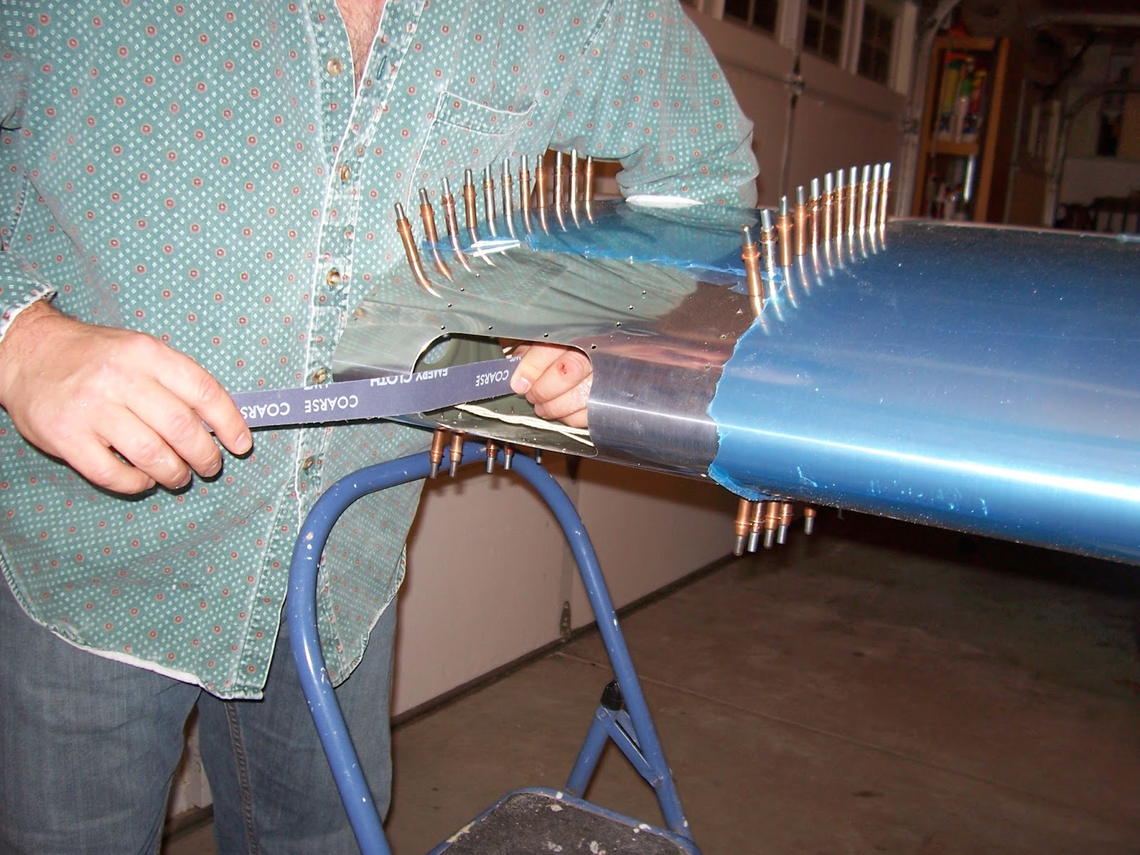
In the final step of cutting out the hole for the landing light I used the deburring tool and sandpaper to make sure that the cutout was burr-free on both sides of the skin. Didn't want to scratch the plexiglass landing light lens during the lens fitting process if I could help it.
I didn't take any pictures of the process of cutting the plexiglass lens and installing the top and bottom backing plates, but as you might guess it also involved a lot of cutting and sanding. Fotunately Mr. B's bandsaw cuts through plexi quite nicely without cracking it and his belt sander did a great job of trimming the plexi down to the required dimensions - basically flush with edges of the lens backing plates. Serendipitously it helped that the sanding belt was mostly worn out from the time I used it on the vertical stabilizer and rudder caps. A fresh sanding belt would have been far too aggressive. I finished the edges of the lens ('radius' is the term used) with 200 grit sandpaper. . 
Per recommendations from builders on the VAF forum , as well as an assessment that there isn't much justification for snug-as-a-bug-in-a-rug holes in the lens as there is elsewhere on the plane, I made the screw holes in the plexiglass slightly oversized to relieve any misalignment stresses and allow for thermal expansion.
