Natomas Follies

VSB - very slow build

Wednesday, October 22, 2014

Sew What?

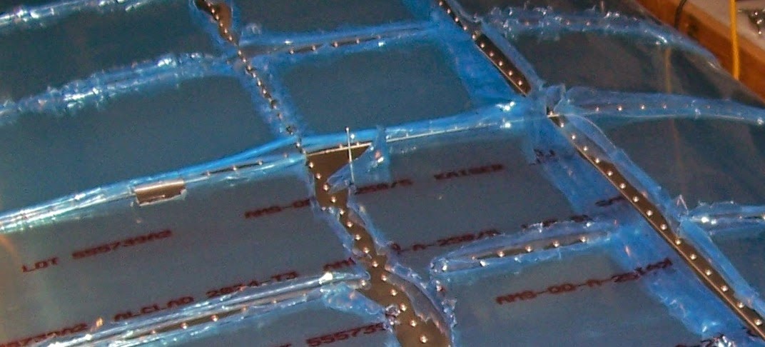
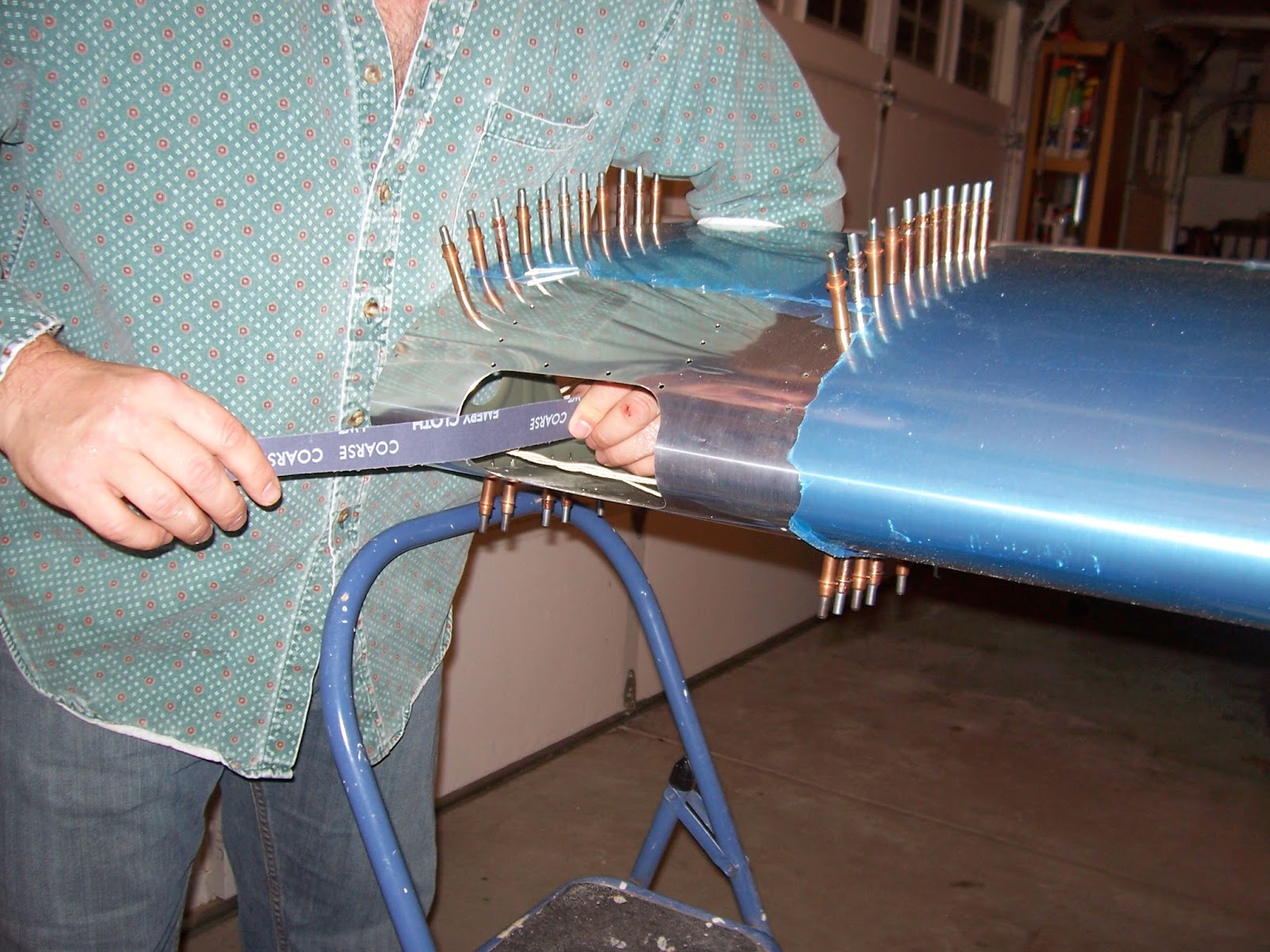
Now that the right wing is done (except for the nav-strobe light and fairing that goes on the wing tip), it was time to hang it out of the way.  In my opinion a wide strap near the outboard end is the way to go.  Luckily for my wallet an RV builder in Davis gave me about 50 feet of fire hose that he no longer needed that fit the need perfectly.  Are airplane builders the nicest people or what?  As an indoor-use hose the outer canvas cladding is surprisingly silky, so I don't have to worry about it scratching the aluminum wing skins.  But first I had to find something that could poke through four layers of lined canvas to sew on D-rings that I bought through berkeleypoint.com

After searching the internet I found what I needed:  The Speedy Stitch Sewing Awl. According to speedystitcher.com,
"The Speedy Stitcher Sewing Awl is a hand tool that can be used to sew any heavy material. It's a handy tool to have around the house, farm, workshop or any place where leather, canvas or vinyl has to be sewn or repaired.
Every Speedy Stitcher is Made in the USA and comes with our high-tensile waxed thread and custom-made diamond point needles. With a little practice, it sews a perfect lock stitch every time - just like a sewing machine.
Uses for the Speedy Stitcher include the assembly and repair of leather goods, canvas tarps, climbing and camping gear, saddlery and tack items, athletic equipment, even shoes and belts."
So I ordered one from Amazon for $12.  A week later I found the same thing at Harbor Freight (or Chinese knock-off, probably) for $8 that included a big bobbin of canvas thread.  Grrr.

Know what else I found at Harbor Freight Sewing and Toiletries Supply Store while shopping for removable chain links?  A cheap ear and nose hair trimmer.  Score!  I've been needing one of those for a while now.  Sorry, is that TMI?


After watching a couple YouTube videos on how to use the durn thing, I went to work.  With three rows of lock-stitching and high-strength thread I feel pretty good about the sewing job I did.  You could probably tow a car with it.  Heck, you could probably lift a car with it.  The wing that this thing will be holding up weighs less than a hundred pounds.  I figure the weakest link is the four-inch lag bolts screwed into the ceiling joists.  I'm not sure how you would estimate the strength on those, but I'm comfortable knowing that there are six lag bolts being deployed for each wing.

A few rows of stitches and the first D-ring was securely sewn on.


Once I double-checked the length needed I cut the hose, sewed a D-ring on the other end, and added a third D-ring in between.  Having three D-rings on the strap gives both low and high strap positions, as we'll see below.


I also had these brass snap-swivel thingys hanging around the garage for the last 12 years and finally found a use for 'em.


Here's the low position D-ring being used to initially hang the end of the wing on the strap until the spar end can be lifted and hung:


Here's the strap in the high position - closer to the ceiling and out of the way.  There's a wood block there to keep the strap from pressing on the upper skin, which extends past the aft wing spar a couple inches...


...So I need to move this ceiling anchor to the left some (which will also put the wing a little closer to the ceiling) but that can wait 'til another day.


Here's the root end of the right wing hanging from a hitching ring mounted on the ceiling.  You can see the left wing skeleton is already back on the work table.  Thank you John-John and Griffin for helping me move the wings.


I removed the latch and filed notches into the inside-bottom of a carabiner so that it's flat against the brass wing spar bushing instead of concentrating weight on the edges of the bushing.


February 23, 2015 Update (aka back from the future):
Finally got around to moving the ceiling anchor d-ring so that the right wing hangs closer to where I wanted relative to all the other stuff in my getting-ever-more-crowded garage.  Here's the pic:

Friday, October 17, 2014

Big Hole, Small Wires

After riveting the main wing skins next up was to install several oddly-shaped skins and ribs that make up the wing tip.  The top ones went on and then it was time to turn the wing over (again, with assistance from neighbor Ken) and close it out with the bottom wing tip skin.

I'm also installing nav lights for night flying, so I needed to cut a hole in the bottom wing tip skin.  Since the wing-tip lights and landing light installation instructions were originally intended to be retrofitted onto a completed wing, Vans instructs builders to cut a fist-sized hole in the bottom skin to order to get a hand in there and fish through wires needed for the lights.  But cutting odd shapes like the one on the provided template into sheet metal ain't that easy.  Furthermore, the big hole is only needed if you are retrofitting the lights and need to get your arm in there to pull wires through.  If you're not doing a retrofit, and you haven't yet closed out (riveted on) the bottom tip skin, then a small drill hole, say 3/8", to pass lighting wires should be sufficient.  In my opinion Vans should have provided a small hole option for builders who are installing lights as they build and finish out the wing.  Alas they did not, and are not likely going to. Since deviation from the plans is not allowed under the ELSA airplane category, I'm stuck cutting a fairly large odd-shaped hole in the wingtip bottom skin whose purpose will be to simply pass three small wires to the wingtip strobe/nav light.

On the Vans Air Force RV-12 forum (thread link here), I posed the question on whether a small hole could be used instead of the big hole.  The answer I got from the unofficial factory rep who monitors forum postings was this:
The answer is really pretty simple... would the hole match what the plans say to do?  If not, then it is not per plans.  So it is obvious, the answer is no.
Would an inspector be able to see it wasn't?  Probably not.  Does that make it right?  You will have to decide that one for your self....
And that's the final word on that.  Scott (aka rvbuilder2002 on the forum) is right of course, so big hole it is.  Sigh.  But really, IMHO Vans should have provided optional/alternative plan instructions for a small hole.  Feel free to comment below if you disagree.  I'll get the flame suit on.  Who knows, maybe it'll help out the next builder who reads this.  Or help me feel better about cutting a 14 square inch hole just to pass three small wires.

    Now on to the pictures.  This is a pic with the top wing tip skins and tip rib riveted on.

     Here is the wing turned upside down (inverted) again.

    Here's the wing tip bottom skin with the hole that I wanted to use.

And here is the bottom wing tip skin with the Vans-supplied template sized hole.  I used a unibit, metal snips, drill with 2-inch sanding drum attachment, and of course the deburring tool.  Helps that the radii of the cutout corners are about 1 inch (same as the sanding drum).  I ended up spending way too much time sanding down to the marked line so for the left wing I'm definitely using the sheet metal nibbler that worked so well on the landing light hole.

The tabs at the top need to be bent down at specific angles in order to match the other tip skins.  A bending tool fabricated from plywood is used to make the bends.  Most of the bends are 30 degrees, some are more and some are less. 30 of the tabs are bent at 30°(nice symmetry eh?), 9 are 31°, 4 are 17°, 3 are 32°, 2 are 28°, and one bend each at 16°, 19°, 20°, 21°, 22°, 24°, 25°, 35°, 41°, 51°, 82°, and 116°, as we shall see a little further on.


Click to enlarge
Personally I think Van's draftsman was having too much fun with this plans page. One degree of bend angle on a half-inch tab is less than 1/100th of an inch -- barely measurable. If the bend is within +/- 5° it'll work. Some builders have some pretty fancy angle-measuring tools but I used my daughter's $2 protractor to mark and cut a bunch of business cards for checking the bend angles.

Bending, checking, and sometimes re-bending all those skin tabs was tedious and I kept putting it off but eventually I got 'em all done.  The result is that the bottom wing tip skin fit like a glove.  I wasn't sure about the location for the bend line for the last tab on the trailing end (and also remember reading something about it on the VAF forum), so I trial-fit the skin onto the wing to visualize how it should go before actually bending it with the tool.  I'm glad I did because the desired bend line is not where I initially thought it'd be.

Above right is a picture of the final aft-most tab without the bend, and the picture to the left shows the bend in the tab.


Finally it was time to cleco on the bottom tip skin for an hour-long session with the pop-rivet squeezer.  Can you tell which tab got the 116° bend?
Below is a pic with the bottom tip skin fully riveted on:

Three rivet holes are left open where a wing tip fairing for the nav-strobe light will be fastened.  The fiberglass fairing will also cover up the access hole.   The open rivet holes are marked No, No, & No, which is what I say to people who ask if the plane is almost done yet.

I saved the leftover rivet mandrels beginning from where I started riveting the first wing skin and then counted 'em up.  It takes 2,128 pop-rivets to skin a wing on the RV-12.


Wednesday, September 17, 2014

Right Wing Skins On

It's been six months since my previous post.  Apologies to friends and family hoping to see steady progress being made.  'Twas summertime in Sacramento you know and usually too warm to hang out in the garage.  At last the days are getting shorter and the Delta breeze has been kicking in making it tolerable to do work in the aircraft factory so I've been riveting on wing skins for an hour here and there the past few weeks.  It's been tedious and there's nothing particularly blog-worthy about that so all I have for now is a few pics of the final result.

First the bottom skins go on (the ones that wrap around the nose), but most of the top-side rivets are left open.  Then the flaperon attach brackets go on (through slots in the bottom skins), then the top skins go on, and then you finish up by lapping the bottom skin over the front of the top skin and adding the wing-walk doubler skin at the wing root.  To the right is a picture of a flaperon attach bracket.


All the Vans wing skins have -inch rivet holes pre-punched at the factory and generally no deburring was required.  In the next picture I'm finishing up the process of lapping the bottom skin over the top skin and fastening with clecos:

Can you see the last rivet in this picture?
No?  How about now:
Bonus points if someone can tell me what the rivet hole is for, since it's not on a wing rib and doesn't connect the skin to anything underneath.

Of course it would look prettier without all the blue plastic on, but for now I like having it to protect the aluminum skins from scratches.

Wednesday, March 19, 2014

Landing Light Cutout

With the right wing skeleton done it's time to start skinning the wing so I can install the landing light.  Before that I need to peel the blue plastic off the expansive wing skins.  On one side anyway.  On the Schmetterling Aviation blog Dave G suggested using a tube to "roll" the sticky plastic off.  Luckily I had some 1-½" PVC pipe lying around that happens to be about the right length so I gave it a shot.

Since the wing is taking up all my limited work space, my truck's tailgate has been getting a lot of use as a second work bench.
An added benefit of Dave's method is being able to unroll the plastic and reuse it as a drop cloth so that I don't spray paint  freckles on the driveway. 

I sprayed self-etching primer along the rivet mating surfaces to inhibit corrosion.


First skin to go on is the W1201R, which is the inboard bottom skin.  The wing skeleton is turned upside down and the bottom skin laid on top of it.  The bottom wing skins are the ones that wrap around the nose of the wing to form the wing leading edge.
It's nice getting help from my 9 year old future co-pilot setting up rivets.  With the extra help riveting the skin on with the hand-squeezer went quickly.  It'd be nice though if Gawdlmuhrt* would finally let me borrow his pneumatic pop-rivet puller so that other family members could pull some rivets too.

*Guy at Work [who] Doesn't Let Me Use His Rivet Tool
Next on is the W1203R skin.  If I haven't mentioned before, there is sometimes a method to Vans parts numbering madness:
W = wing (duh),
12 = Vans RV-12,
03 = third wing skin (from inboard),
R = right, or starboard wing (really??)

The middle skin, the W1202R, edge-overlaps the inboard and outboard skins and therefore goes on last.
Since the landing light gets installed way out on the outboard end of the wing, the # 3 bottom skin is where things start to get - shall we say - interesting.   In case I ruin the skin cutting the hole for the landing light and have to order a replacement skin, I held off riveting and just attached it with clecos.  All the clecos I had available were used.
The first step in the landing light installation is taping a hole cutout template at an exact location and marking the top of the hole cutout, screw holes and rivet holes.


A couple taps with an awl marks the various drill locations on the skin indicated on the template.  The tiny dent made with the awl helps keep the drill bit from wandering before it starts to bite into the aluminum.


After the hole locations are marked it's time to drill.  Not particularly efficient, but I usually start with my smallest drill bit and work my way up through each bit 'til I get the hole size I want.


So far so good.


I don't recommend using a saw for cutting round holes in wood doors on aircraft aluminum, but that's what I had available and somehow it worked.  I just kept a very firm grip on the drill and relatively light pressure while drilling.  In hindsight a unibit might have worked better, but then again maybe not.
At light pressure it took a while but eventually the hole saw cut through and I had the starter holes I needed.
Once I had the top holes it was time to flip the wing upside down and, once again using the template, mark the cutout for the bottom of the landing light opening as well as the remaining screw and rivet holes.
 .... and the hole-drilling process is repeated for the bottom side: 
By the time I was finished with the hole saw it looked like this:

From here I used the tin snips and a pneumatic nibbler to cut out the opening for the landing light (sorry - no pictures).  It was my first time using Mr. B's sheet metal nibbler and was amazed how well it worked - literally hot knife through butter.  If I'd known how nicely it shears through sheet metal without deforming the edge like snips sometimes do I probably would have gone with the easy-to-use unibit instead of the hole saw for the initial holes.  I never even touched the die grinder/cutoff wheel - the one tool that the plans said was needed for this task.  The plan directions weren't exactly followed to the letter either.  Vans' Section 40 instructions for installing the lights assume that the wings are already finished, which in my case is not the case.  So it took a bit of extra reading and thinking to figure it out prior to commencing work.
 
Each corner of the cutout has a one-inch radius so the tool I used next was a two-inch diameter sanding drum.  It came in a set that I picked up at Harbor Freight Aircraft Tools and Supply store for about $8.  In no time the sanding drum gave me the nicely rounded corners that I was shooting for.
Once work with the sanding drum was finished, final finishing was done with with a metal file and strips of sand paper.  This is why you want to install the light before you put the top skin on.  I can't imagine trying to do this without access from behind.

It took a few hours final-shaping and smoothing the hole, but I wanted it to stand up to scrutiny from other RV builders.  Turnabout is fair play so I, of course, will be surreptitiously paying close attention to their landing light cutouts.

In the end I managed not to crease or ruin the skin so I'm relieved that that's over with.

In the final step of cutting out the hole for the landing light I used the deburring tool and sandpaper to make sure that the cutout was burr-free on both sides of the skin.  Didn't want to scratch the plexiglass landing light lens during the lens fitting process if I could help it.


I didn't take any pictures of the process of cutting the plexiglass lens and installing the top and bottom backing plates, but as you might guess it also involved a lot of cutting and sanding.  Fotunately Mr. B's bandsaw cuts through plexi quite nicely without cracking it and his belt sander did a great job of trimming the plexi down to the required dimensions - basically flush with edges of the lens backing plates.  Serendipitously it helped that the sanding belt was mostly worn out from the time I used it on the vertical stabilizer and rudder caps.  A fresh sanding belt would have been far too aggressive.  I finished the edges of the lens ('radius' is the term used) with 200 grit sandpaper. . 

Per recommendations from builders on the VAF forum , as well as an assessment that there isn't much justification for snug-as-a-bug-in-a-rug holes in the lens as there is elsewhere on the plane, I made the screw holes in the plexiglass slightly oversized to relieve any misalignment stresses and allow for thermal expansion. 

And here it is with the landing light lens installed.  Although it's not perfect, the cutout hole looks good, the skin around it looks good, and the lens is about as flush with the [inside] wing skin as I can get it.  Overall it turned out well.  The rest of the wings build should be all downhill from here and I'm hoping to be done with 'em before it starts to get hot around Sacramento 'cause I am not building in the heat!