
Kevin's RV-12 VSB Builder's Log
Thursday, February 20, 2014
Wednesday, January 29, 2014
Flaperons Finished
The CFO thought it was funny whenever I said that I'm going out to work on the flaperons. She thinks it's something that makes the toilet flush and that I'm just making up names for stuff to yank her chain (rimshot). So I'm tempted to refer to them by their more well-known name: ailerons. Ehh... Nah.
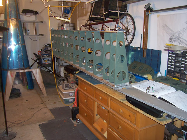
Other than the post title I can't say that I have anything interesting to report so I'm just going to post a few pictures wrapping up the build of theailerons flaperons. Each flaperon consists of a main spar, 14 ribs (12 are isoceles triangles and 2 are "D" shaped, one of which also has a doubler riveted on), 2 brackets for the counterbalance, a stainless steel counterbalance pipe, 2 AEX pivot brackets, an actuation bracket, 2 rib skins, 3 nose skins, and of course lots of pop rivets. Here is all the parts needed to make a flaperon:

Here I'm riveting the outboard nose skin onto the left flaperon. The outboard nose skin is the one that covers and attaches to the counterbalance pipe. Without the counterbalance you can imagine the flaperons flapping around in bumpy air with some highly undesireable results such as aileron flutter. The hole is where the hinge bracket attaches to a threaded bearing rod.

Peeling back just enough enough to uncover the rivet holes, I left as much of the blue plastic on as I could to protect the skins during their long stay in storage (VSB, remember). I'll check on them from time to time to make sure the adhesive doesn't start to harden, which happens when exposed to a lot of UV light. RV builders who've let that happen regret not removing the blue plastic sooner but so far it still peels off easily.

And this is me finishing the last few rivets in right wing flaperon.

As happened many times before, often a pop-rivet didn't want to go in the hole. If holes in the skin and the underlying rib (or bracket, as the case may be) are mis-aligned by a hundredth of an inch it can cause the rivet to not go in. Because of small indentations on the rivet, I discovered that by turning the rivet 90 degrees sometimes that will be enough to slip the rivet in. If that doesn't work, try 180 and 270. If that doesn't work more aggressive measures (such as reaming out the hole) may be necessary, but usually not. I had to use the awl or #30 fluted reamer on just a few holes on each flaperon. Most of the time just putting a new cleco (as opposed to a worn cleco. I have, and use, both, depending on the situation) in the hole and then removing it would get the holes sufficiently aligned for a rivet to go in - it helps to have both (old and new) on hand.
Finally I pulled down the 15-foot main spar for the right wing with assistance from neighbor Mike and put the finished flaperons away for storage. Now looking forward to starting the right wing skeleton followed by the landing light installation. Because of the need to cut a rectangular hole in the outboard nose skin and then trim and flush-fit a plexi (Lexan™) lense, the landing light installation may be the hardest challenge yet.
Other than the post title I can't say that I have anything interesting to report so I'm just going to post a few pictures wrapping up the build of the
Here I'm riveting the outboard nose skin onto the left flaperon. The outboard nose skin is the one that covers and attaches to the counterbalance pipe. Without the counterbalance you can imagine the flaperons flapping around in bumpy air with some highly undesireable results such as aileron flutter. The hole is where the hinge bracket attaches to a threaded bearing rod.
Peeling back just enough enough to uncover the rivet holes, I left as much of the blue plastic on as I could to protect the skins during their long stay in storage (VSB, remember). I'll check on them from time to time to make sure the adhesive doesn't start to harden, which happens when exposed to a lot of UV light. RV builders who've let that happen regret not removing the blue plastic sooner but so far it still peels off easily.
And this is me finishing the last few rivets in right wing flaperon.
As happened many times before, often a pop-rivet didn't want to go in the hole. If holes in the skin and the underlying rib (or bracket, as the case may be) are mis-aligned by a hundredth of an inch it can cause the rivet to not go in. Because of small indentations on the rivet, I discovered that by turning the rivet 90 degrees sometimes that will be enough to slip the rivet in. If that doesn't work, try 180 and 270. If that doesn't work more aggressive measures (such as reaming out the hole) may be necessary, but usually not. I had to use the awl or #30 fluted reamer on just a few holes on each flaperon. Most of the time just putting a new cleco (as opposed to a worn cleco. I have, and use, both, depending on the situation) in the hole and then removing it would get the holes sufficiently aligned for a rivet to go in - it helps to have both (old and new) on hand.
Finally I pulled down the 15-foot main spar for the right wing with assistance from neighbor Mike and put the finished flaperons away for storage. Now looking forward to starting the right wing skeleton followed by the landing light installation. Because of the need to cut a rectangular hole in the outboard nose skin and then trim and flush-fit a plexi (Lexan™) lense, the landing light installation may be the hardest challenge yet.
Friday, January 10, 2014
Easiest Steps in the Build
The easiest steps in the build are Page 18-02 Steps 1 and 2, which has us fabricate left and right flaperon actuation brackets from ⅛-inch aluminum angle, and four flaperon pivot brackets from AEX extrusion as shown in Figures 1 and 2.

What makes these so easy you ask? They certainly don't look easy. It's because Vans went ahead and did the fabrication for me, so the parts are already done:

They did a nice job too. Checking the builder blogs I read that some folks had a hard time fabricating these and had to reorder stock aluminum from Vans for a do-over. At some point in the last year or two somebody at Vans finally said "You know what? Builders are having a hard time with these. We should just fabricate a bunch of these (or contract it out) and include 'em in the wing kit." So there it is. To all the early builders who were flummoxed while fabricating their own brackets, all I can say is BWAHAHA! ; -)
Second runner-up for easiest steps in the build are Page 18-04 Steps 4, 5, 6 and 7, which has us match drill rivet holes in the A1206 pivot brackets and A1207 actuation bracket. Again, Van's already did all the work (see picture above) and the holes matched up perfectly where they were supposed to go on the flaperon spar. Love it when that happens. The "second-runner up" status is owed to the fact that the instructions say to prime these parts before installing, which didn't take long. I think it's because of the fact that steel rod-bearing bolts will be screwed in (or attached) to the brackets. Unprotected steel in contact with unprotected aluminum = flow of electrons = eventual corrosion. I went ahead and primed the entire flaperon spar, ribs, and stainless steel counterbalance as well, "just because".
 Third runner-up for easiest steps in the build is Page 18-02 Step 3. All I did is add some flutes at the prescribed locations on some flaperon counterbalance end brackets to flatten 'em out. Here's a picture:
The flutes are added to flatten out the natural arch in the piece which comes from the factory stamping and forming process.
Here are before and after shots that show the arch being flattened after pinching a couple flutes to the work piece:


And here they all done, along with the fluting tool I borrowed from Mr. B:

So Page 18-02 took about 10 minutes and it was done.
What makes these so easy you ask? They certainly don't look easy. It's because Vans went ahead and did the fabrication for me, so the parts are already done:
They did a nice job too. Checking the builder blogs I read that some folks had a hard time fabricating these and had to reorder stock aluminum from Vans for a do-over. At some point in the last year or two somebody at Vans finally said "You know what? Builders are having a hard time with these. We should just fabricate a bunch of these (or contract it out) and include 'em in the wing kit." So there it is. To all the early builders who were flummoxed while fabricating their own brackets, all I can say is BWAHAHA! ; -)
Second runner-up for easiest steps in the build are Page 18-04 Steps 4, 5, 6 and 7, which has us match drill rivet holes in the A1206 pivot brackets and A1207 actuation bracket. Again, Van's already did all the work (see picture above) and the holes matched up perfectly where they were supposed to go on the flaperon spar. Love it when that happens. The "second-runner up" status is owed to the fact that the instructions say to prime these parts before installing, which didn't take long. I think it's because of the fact that steel rod-bearing bolts will be screwed in (or attached) to the brackets. Unprotected steel in contact with unprotected aluminum = flow of electrons = eventual corrosion. I went ahead and primed the entire flaperon spar, ribs, and stainless steel counterbalance as well, "just because".
Third runner-up for easiest steps in the build is Page 18-02 Step 3. All I did is add some flutes at the prescribed locations on some flaperon counterbalance end brackets to flatten 'em out. Here's a picture:The flutes are added to flatten out the natural arch in the piece which comes from the factory stamping and forming process.
Here are before and after shots that show the arch being flattened after pinching a couple flutes to the work piece:
And here they all done, along with the fluting tool I borrowed from Mr. B:
So Page 18-02 took about 10 minutes and it was done.
Thursday, January 9, 2014
Building out of order
After building the left wing skeleton the next step is to... build the right wing skeleton! Makes sense, right? I'm going to go out of order by building the flaperons next, and this post explains why. See my work area is a 4'x8' sheet of plywood cut lengthwise and fastened onto an old bedroom dresser with piano hinges and screws. Castoring wheels were fixed to the feet so I can move it around. It's been a good low-cost work table solution for building and skinning things like 15-foot airplane wings. In the later stages of the build when the big parts start to come togther (fuselage, tailcone, landing gear, etc.) I'll be able to free up necessary airplane storage space by donating it to the next RV builder newbie or just getting rid of it.

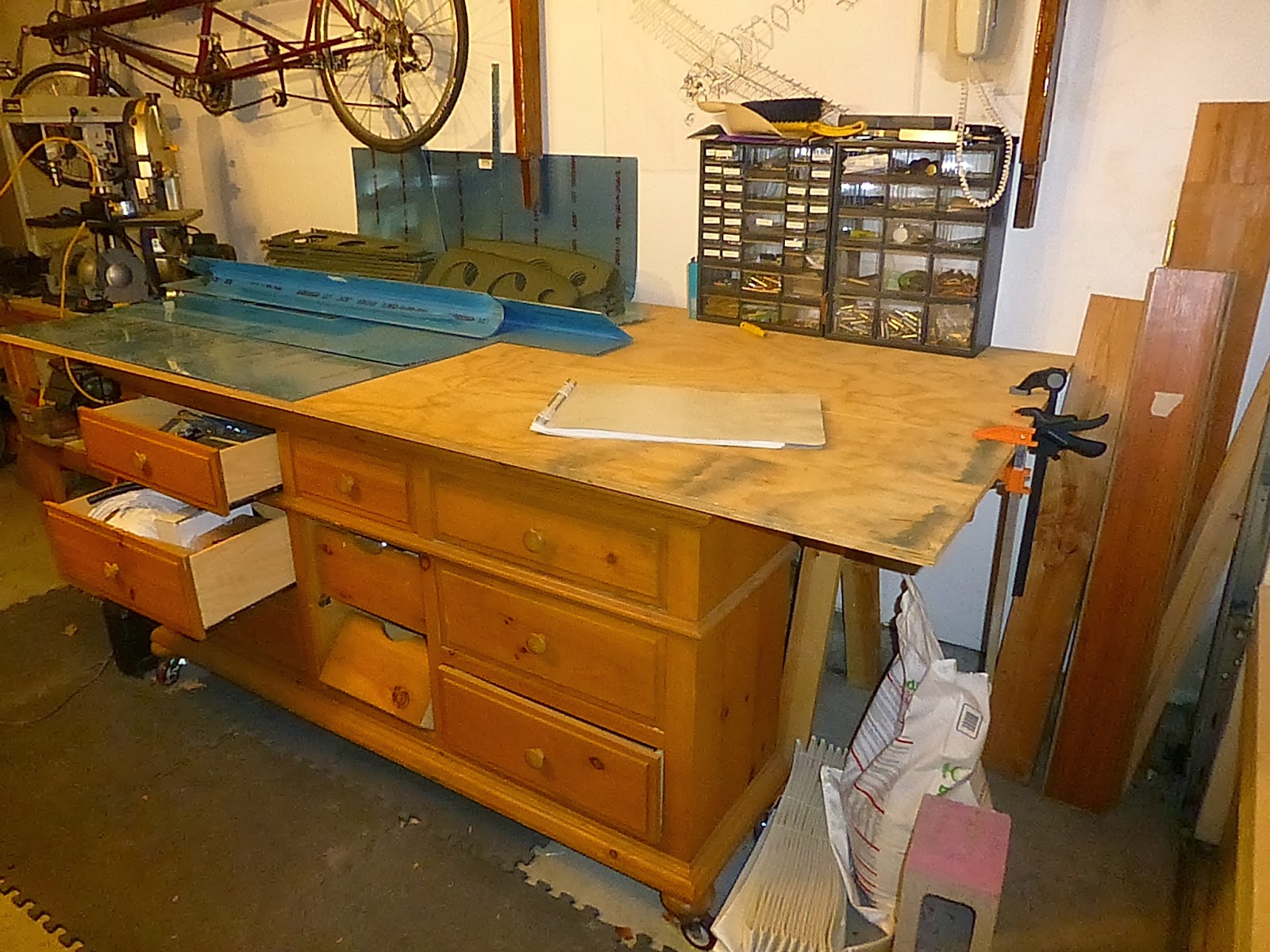
In the interim, and somewhat unintentionally, it has also been the place where I've stored the wing ribs, skins and parts. Smaller parts, such as wing lights and various brackets go in the drawers, hidden and out of the way. Really small parts such as nuts, bolts, rivets, drill bits, and the like go into small parts tray racks on loan from Mr. B.
By reading ahead in the plans, particularly the sections on skinning the wings (Section 17), closing out the wing tips (17-05 & -06), and installing the landing and position lights (Section 40), it's become obvious to me that I'm going to need to clear off the table for the upcoming building tasks. By doing the flaperons (flaps + ailerons = flaperons) next and subsequently storing them elsewhere and then doing the right wing skeleton, I can reduce the loose parts count leaving pretty much just the wing skins (which I can probably store on top of the left wing skeleton hanging from the ceiling), and a few parts for the wing tips thus restoring the work table back to its original utility to facilitate the skinning and wing lights installation. So that's the reason for going out of order.
Sunday, January 5, 2014
Left wing stored
With help from a neighbor I hung the left wing skeleton from the ceiling to make room for building the right wing skeleton. Here's a few pictures of it hanging a few inches from the ceiling and slightly overlapping my sadly underused home-built kayak. Hope the plane doesn't suffer a similar fate. I really enjoy taking the kayak out on the water for the upper body workout if nothing else, but can never find a potential drowning victim paddler to go out with. A tandem kayak with only one person in it is quite the sight because the nose is so high out of the water without the extra weight in front. Remember the movie 'Shallow Hal' when Hal goes out on a canoeing date? It's something like that. When I take my nine-year old out to the river I have to add an additional 70 lbs of dumbells (rolled up in bubble wrap) in the bow to get the nose down to level in the water. She uses her kid-sized paddle and I use a 6 foot adult size. Guess which one of us does all the work. Still, it's a lot of fun.
 Here's the other end of the wing skeleton hanging from a strap of unknown origins. Based on the Graco tag, it may have secured a baby car seat in its former life but no one seems to remember using it. The D-ring and O-ring are from Harbor Freight and they're screwed into the ceiling joists with 2.5 inch lag bolts.

And finally the obligatory tunnel shot:

Now I can start on the right wing skeleton.


And finally the obligatory tunnel shot:

Now I can start on the right wing skeleton.
Friday, January 3, 2014
Stall Warning Switch
Happy New Year! Hope your New Years Eve was safe and fun. The CFO and I went to Old Sacramento to enjoy the midnight fireworks show on the waterfront. Crowded, but festive! Afterwards we had a 1:00 am dinner-breakfast at Denny's. The young-un got to go to a sleep-over with a bunch of other rambunctious nine and ten-year old girls at a friend's house. I heard they got about three hours sleep. I'd say they did pretty well.
New Year's day I assembled the stall warning switch, screwed it to one of the forward wing ribs, wired it up, and ran some kite string through the length of the wing for pulling the wiring for the wing tip position lights later on. Also ran a couple extra strings just in case I add a left-side landing light sometime in the future (the plans have the landing light on the right side only). Right and left landing lights, especially in the pulsing "wig-wag" mode, would add a nice symmetry and make the airplane more visible. But for now we stick to the plans.
Wiring the stall warning switch necessitated the purchase of another pair of terminal crimpers to attach connectors on the ends of the wires. Well one end anyway. The TERMINAL INSTALLATION TABLE on page 5-14 of the plans recommends the "TH-450", which Google reports as costing somewhere between $48 and $752.95. Yikes! What is it about aviation-related parts and tools?? Thankfully some Chinese businessman thought he could make 'em cheaper and sell knockoffs at Harbor Freight, so faithful to my miserly tendancies I bought this one instead (The red one, not the yellow one. The yellow one I picked up at Frys when I was doing the wiring connector for the aft servo).

With a 25% off coupon it was $7.50 plus tax. Thank you HF!
Between the two pairs of crimpers I should be able to crimp any electrical connector likely to be found on an airplane. Or hopelessly mangle untold numbers of electrical terminals, which could also happen with the $753 crimpers.
Here's the stall warning switch mounted on the rib:

What I didn't do, even though it's the next step in the plans, is peel off the blue plastic and cleco on the middle front wing skin in order to set the adjustment on the position of the switch and bend on the stall warning tab "if necessary". The instructions are a bit confusing and I'd like to get some assistance on this from someone who's done it before. I may have to actually attend a local EAA chapter meeting to beg for help. Problem is that I think only one of the local EAA members has built an RV-12, but maybe it's the same for all Vans RV's. I'll have to check. There's a chance that, by setting it at the mid-range position, that it won't need any adjustment. Wouldn't that be splendid?! I'm also going to round the corners on the stall warning tab with a file. The protruding corners on that thing look like a flesh wound waiting to happen.
Regarding the wing storage issue, I purchased a couple items to hang one end of the left wing from the ceiling for when I get ready to start the right wing skeleton, possibly as soon as this weekend. The D-ring anchor (mounted on the ceiling in the picture below) was also from Harbor Freight. The packaging says it "Mounts to Floor of Trailer or Truck Bed" and is "Not for lifting" However the stated working load is 233 lb and the breaking strength is 700 lb, so I assume that hanging one end of an 85 lb wing on it will be okay. I used a couple of fairly beefy lag bolts and screwed 'em tightly into the center of the ceiling/floor joists, which run left to right. It could probably hold several hundred pounds, but I'm not anxious to find out what the rip-the-bolts-out-of-the-ceiling-joists yield strength is. I made sure that the ceiling anchor was out of the way of the garage cabinet doors, but the CFO voiced concern about the location over the hood of her car by asking why I couldn't just put it on the other side of the garage. You know, my side. Had to explain that that's where the other wing will go. In a month. Or two. Three at the most. Okay four. Love you honey!

New Year's day I assembled the stall warning switch, screwed it to one of the forward wing ribs, wired it up, and ran some kite string through the length of the wing for pulling the wiring for the wing tip position lights later on. Also ran a couple extra strings just in case I add a left-side landing light sometime in the future (the plans have the landing light on the right side only). Right and left landing lights, especially in the pulsing "wig-wag" mode, would add a nice symmetry and make the airplane more visible. But for now we stick to the plans.

With a 25% off coupon it was $7.50 plus tax. Thank you HF!
Between the two pairs of crimpers I should be able to crimp any electrical connector likely to be found on an airplane. Or hopelessly mangle untold numbers of electrical terminals, which could also happen with the $753 crimpers.
Here's the stall warning switch mounted on the rib:

What I didn't do, even though it's the next step in the plans, is peel off the blue plastic and cleco on the middle front wing skin in order to set the adjustment on the position of the switch and bend on the stall warning tab "if necessary". The instructions are a bit confusing and I'd like to get some assistance on this from someone who's done it before. I may have to actually attend a local EAA chapter meeting to beg for help. Problem is that I think only one of the local EAA members has built an RV-12, but maybe it's the same for all Vans RV's. I'll have to check. There's a chance that, by setting it at the mid-range position, that it won't need any adjustment. Wouldn't that be splendid?! I'm also going to round the corners on the stall warning tab with a file. The protruding corners on that thing look like a flesh wound waiting to happen.
Regarding the wing storage issue, I purchased a couple items to hang one end of the left wing from the ceiling for when I get ready to start the right wing skeleton, possibly as soon as this weekend. The D-ring anchor (mounted on the ceiling in the picture below) was also from Harbor Freight. The packaging says it "Mounts to Floor of Trailer or Truck Bed" and is "Not for lifting" However the stated working load is 233 lb and the breaking strength is 700 lb, so I assume that hanging one end of an 85 lb wing on it will be okay. I used a couple of fairly beefy lag bolts and screwed 'em tightly into the center of the ceiling/floor joists, which run left to right. It could probably hold several hundred pounds, but I'm not anxious to find out what the rip-the-bolts-out-of-the-ceiling-joists yield strength is. I made sure that the ceiling anchor was out of the way of the garage cabinet doors, but the CFO voiced concern about the location over the hood of her car by asking why I couldn't just put it on the other side of the garage. You know, my side. Had to explain that that's where the other wing will go. In a month. Or two. Three at the most. Okay four. Love you honey!

Soon I'll hang the spar end (not the outboard end) of the left wing here to get it out of the way so I can start the right wing. The caribineer I picked up at REI for $6 slips into one of the spar pin holes, the ones with the big brass bushings. It's actually made for rock climbing so I had to modify (i.e., ruin) it with the drill press to remove the spring-loaded latch thingy. I'm not sure what the yield strength on a ¼-inch carabineer is but it's a lot, even with one side missing. It doesn't show in the picture, but I also filed it a little so that weight wouldn't be concentrated on the rim edge of the brass bushing. Luckily it turns out the thickness of the wing spar on the beefy end is about the same as the width of a regular metal file. The other end of the wing will probably require a strap of some sort, but I'm not quite sure yet what I have lying around.
Friday, December 27, 2013
Left Wing Ribs done
Finished attaching nose ribs and the front stub spar over Christmas. Building space in the garage has suddently become an issue and will probably get worse before it gets better. I'll need to figure out how to hang the wings from the garage ceiling in a way that's secure but easy to retrieve. I've an idea or two that may work while the wing is still a skeleton, but not once it's skinned. I've got another idea that will work once the wings are skinned, but not in the interim. We'll see how it goes.

Most of the nose ribs went on easily enough but a few of the inboard ones were tricky because, as you can see in the photo below, there's not enough room to get the rivet tool square on the rivets.
 So once again we use the wedge-thingy to squeeze the rivets at an angle. Problem I had is that it typically takes two or three squeezes to "pop" the rivet and between squeezes when the tension is relaxed the wedge wants to turn 90 degrees or so on the rivet mandrel "heavy"-side down, which is unhelpful and annoying. Some of the factory holes in the main wing spar had to be reamed out a little with a #30 fluted reamer beforehand in order to get the LP4-4 rivets to go in the hole.
All of the rivet mandrels broke off clean where they were supposed to and the rivet heads were tight on the flanges, which means I didn't have to drill any out and re-do them, which would have been difficult because there's no room to get my fat DeWalt drill in there. Overall it went well.
Having read the warnings of fellow builder-bloggers to follow plan directions very carefully here, it was with some consternation that I noted the instruction on pp 15-05, Figure 1 to use W-1208 -R FWD AND AFT TRIMMED [RIB] WITH 3 ATTACHED NUTPLATES on the last (most inboard) nose rib. The rib I had prepped for this location only had one nutplate on it and a small doubler plate. How the heck did I screw that up? I desperately scanned other builder blogs but no-one else mentioned a problem. So I called Vans builder support Christmas eve before closing and confirmed that it was bascially a typo. Apparently the rib-prep instructions on pp 15-02, Step 9, Figure 4 had been revised in 2011 to add one nutplate and a doubler (instead of three nutplates and no doubler), but the figure on pp 15-05 (indicating three nutplates instead of one on that rib) hadn't been revised, at least not in my set of plans. That was a relief! Just wish someone on VAF had mentioned it. Although fairly minor, builders on VAF will often mention these sorts of things to keep other builders from getting too worked up, especially on weekends, evenings, and holidays when Vans is closed. Ah well.
_________________________________________________________________________
December 30, 2013 Update:
Here's the e-mail I sent Christmas Eve morning to Vans:
On pp 15-02, Step 9 & Figure 4, we are instructed to add a doubler plate and a nut plate to a L and R fwd rib trimmed fore and aft. Note that there is just one K1000-08 nut plate in Figure 4.

Most of the nose ribs went on easily enough but a few of the inboard ones were tricky because, as you can see in the photo below, there's not enough room to get the rivet tool square on the rivets.
 So once again we use the wedge-thingy to squeeze the rivets at an angle. Problem I had is that it typically takes two or three squeezes to "pop" the rivet and between squeezes when the tension is relaxed the wedge wants to turn 90 degrees or so on the rivet mandrel "heavy"-side down, which is unhelpful and annoying. Some of the factory holes in the main wing spar had to be reamed out a little with a #30 fluted reamer beforehand in order to get the LP4-4 rivets to go in the hole.
 All of the rivet mandrels broke off clean where they were supposed to and the rivet heads were tight on the flanges, which means I didn't have to drill any out and re-do them, which would have been difficult because there's no room to get my fat DeWalt drill in there. Overall it went well.
Having read the warnings of fellow builder-bloggers to follow plan directions very carefully here, it was with some consternation that I noted the instruction on pp 15-05, Figure 1 to use W-1208 -R FWD AND AFT TRIMMED [RIB] WITH 3 ATTACHED NUTPLATES on the last (most inboard) nose rib. The rib I had prepped for this location only had one nutplate on it and a small doubler plate. How the heck did I screw that up? I desperately scanned other builder blogs but no-one else mentioned a problem. So I called Vans builder support Christmas eve before closing and confirmed that it was bascially a typo. Apparently the rib-prep instructions on pp 15-02, Step 9, Figure 4 had been revised in 2011 to add one nutplate and a doubler (instead of three nutplates and no doubler), but the figure on pp 15-05 (indicating three nutplates instead of one on that rib) hadn't been revised, at least not in my set of plans. That was a relief! Just wish someone on VAF had mentioned it. Although fairly minor, builders on VAF will often mention these sorts of things to keep other builders from getting too worked up, especially on weekends, evenings, and holidays when Vans is closed. Ah well.
_________________________________________________________________________
December 30, 2013 Update:
Here's the e-mail I sent Christmas Eve morning to Vans:
Dear Vans:
On pp 15-02, Step 9 & Figure 4, we are instructed to add a doubler plate and a nut plate to a L and R fwd rib trimmed fore and aft. Note that there is just one K1000-08 nut plate in Figure 4.
Now moving ahead to pp 15-05, Step 5, we are to attach a
trimmed forward R rib with attached nutplates (plural). (No mention of the doubler plate). It
is the last (i.e., most inboard) rib to go on the L wing. Figure 1
seems to show two nutplates, and the leaderline says W-1208-R FWD AND AFT TRIMMED WITH 3 ATTACHED
NUTPLATES. Page 15-02 was revised 7/12/2011, page 15-05 has not been revised.
I either made a mistake and grabbed the wrong rib,
misread the instructions & missed or a step, or else I am
seriously confused. But I think it might be an error on the drawing.
Question: Is the
inboard-most fwd rib on the W-1206-L wing spar supposed to have one nutplate, two nutplates, or three,
and is it supposed to have the small doubler plate on it?
Thanks for getting back to me.
Merry Christmas
The 3 nutplates went away when the new blue wing root
connectors were adopted. A couple drawings have yet to catch up. One doubler, one nutplate.
Tuesday, December 17, 2013
Wing Rib Prep
When I updated on my building progress in July I was in the middle of Section 14 and had finished riveting four hinge bracket assemblies. I've since wrapped up Section 14 by:
 In Section 15 we prep the wing ribs. As noted in my last blog post, Page 15-02, Step 1, says to "Flute and straighten all of the W-1208 Nose Rib flanges." Page 15-03, Step 1, also has us "Flute and straighten all of the W-1210 Main Rib flanges." That's 26 main ribs and 28 nose ribs. Contrary to my previous post (starring my lovely and talented daughter
 playing practicing theme music for Mission Impossible on her flute) "fluting" is done using fluting pliers to flatten out the ribs, which arrive from the factory with a slight curve in them from the forming/stamping process. But that's not the main reason for fluting. The main reason is to get a straight line of rivet holes on the rib flanges. That's necessary because the pre-punched holes on the wing skins are straight as can be and you absolutely must have them line up with the holes on the ribs or you'll really struggle to insert the skin rivets.
54 wing ribs is a lot of ribs to flute so it took a while - several weeks in fact. It just wasn't a task to get excited over because it's monotonous, tedious, and there's nothing to show for it but an imperceptibly flatter stack of ribs. The only advice I would pass along to other wing builders is that shallower flutes between each rivet hole (i.e. each rib flange tab) seems to work better than deeper (but fewer) flutes in getting a straight line of rivet holes in the rib flanges. The natural arch in the factory rib is fairly uniformly distributed, so the flutes should be too, right?
For some reason nearly all of the center lightening holes had a bit of roughness from the factory stamping process and it seemed like something that should be smoothier. Has to do with the initiation and propagation of stress cracks in sheet metal. Or something like that. Since there are three lightening holes per rib there were 162 holes to sand smooth. I initially tried using the swivel deburring tool but it didn't seem to work well on holes that big, so I ended up using several sheets of high quality (cloth backing) sand paper to smooth the rough edges. Your results may vary.
After fluting and sanding there was still more prep work left. 13 (of 14) left nose ribs get their aft flanges cut off (Page 15-02, Step 2). Could have used the band saw but for the most part metal snips worked better. Then more sanding along the cut line. Then all of the right main ribs had their flanges removed (Page 15-03, Step 3), along with half of the left main ribs (Step 2). Five left nose ribs have the forward-most upper & lower flanges snipped off (to make room to attach the foward stub spar) and for those I used regular office scissors since the metal snips were too awkward to use there. And yes, you can cut aircraft alumninum with office scissors (if your fingers are strong enough). Weird, huh?
Finally nutplates were added here and there to attach the stall warning switch and electrical plug. Two main ribs get doublers attached and the flaperon hinge brackets are match drilled to be riveted on later. Then there was priming to do. I lost count of the number of five-dollar rattle cans I went through as I put multiple coats of self-etching primer on each rib for uniform coverage, while simultaneously wondering whether I'm wasting time and money trying to protect al-clad aluminum, which is already corrosion resistant, especially in a low-humidity area like Sacramento. Eventually (as in, it took me a couple months) the ribs were prepped and ready to rivet. Once again neighbor Ken helped me take the left main spar down from an overhead rack to the work table so I could start turning it into an airplane wing. They're light enough for one person, but as Dave G noted, in tight quarters the main spars can be 15½ feet of mayhem if you're not careful. The picture below shows the four stacks of wing ribs ready to go: L & R main ribs and L & R nose ribs. Interestingly, it's mostly right ribs that go on the left wing, and left ribs that go on the right wing. More Van's humor, that.

 With the ribs now prepped I could finally start attaching main ribs to the left main wing spars - visible progress just in time for the arrival of holiday guests.
- riveting together two more spar hinge assemblies (Page 14-02). (Picture below.)
- attached the hinge assemblies to the aft wing spars and doublers (Page 14-03). (The doublers have a round tip that slips into the fuselage); and
- attached the curved tip angles to the rear spars.
 In Section 15 we prep the wing ribs. As noted in my last blog post, Page 15-02, Step 1, says to "Flute and straighten all of the W-1208 Nose Rib flanges." Page 15-03, Step 1, also has us "Flute and straighten all of the W-1210 Main Rib flanges." That's 26 main ribs and 28 nose ribs. Contrary to my previous post (starring my lovely and talented daughter
 54 wing ribs is a lot of ribs to flute so it took a while - several weeks in fact. It just wasn't a task to get excited over because it's monotonous, tedious, and there's nothing to show for it but an imperceptibly flatter stack of ribs. The only advice I would pass along to other wing builders is that shallower flutes between each rivet hole (i.e. each rib flange tab) seems to work better than deeper (but fewer) flutes in getting a straight line of rivet holes in the rib flanges. The natural arch in the factory rib is fairly uniformly distributed, so the flutes should be too, right?
For some reason nearly all of the center lightening holes had a bit of roughness from the factory stamping process and it seemed like something that should be smoothier. Has to do with the initiation and propagation of stress cracks in sheet metal. Or something like that. Since there are three lightening holes per rib there were 162 holes to sand smooth. I initially tried using the swivel deburring tool but it didn't seem to work well on holes that big, so I ended up using several sheets of high quality (cloth backing) sand paper to smooth the rough edges. Your results may vary.
After fluting and sanding there was still more prep work left. 13 (of 14) left nose ribs get their aft flanges cut off (Page 15-02, Step 2). Could have used the band saw but for the most part metal snips worked better. Then more sanding along the cut line. Then all of the right main ribs had their flanges removed (Page 15-03, Step 3), along with half of the left main ribs (Step 2). Five left nose ribs have the forward-most upper & lower flanges snipped off (to make room to attach the foward stub spar) and for those I used regular office scissors since the metal snips were too awkward to use there. And yes, you can cut aircraft alumninum with office scissors (if your fingers are strong enough). Weird, huh?
Finally nutplates were added here and there to attach the stall warning switch and electrical plug. Two main ribs get doublers attached and the flaperon hinge brackets are match drilled to be riveted on later. Then there was priming to do. I lost count of the number of five-dollar rattle cans I went through as I put multiple coats of self-etching primer on each rib for uniform coverage, while simultaneously wondering whether I'm wasting time and money trying to protect al-clad aluminum, which is already corrosion resistant, especially in a low-humidity area like Sacramento. Eventually (as in, it took me a couple months) the ribs were prepped and ready to rivet. Once again neighbor Ken helped me take the left main spar down from an overhead rack to the work table so I could start turning it into an airplane wing. They're light enough for one person, but as Dave G noted, in tight quarters the main spars can be 15½ feet of mayhem if you're not careful. The picture below shows the four stacks of wing ribs ready to go: L & R main ribs and L & R nose ribs. Interestingly, it's mostly right ribs that go on the left wing, and left ribs that go on the right wing. More Van's humor, that.

 With the ribs now prepped I could finally start attaching main ribs to the left main wing spars - visible progress just in time for the arrival of holiday guests.
Merry Christmas everyone!

Thursday, October 17, 2013
Fluting the ribs
Over 3 months since I last posted. Not a very good blog is it? I pretty much took the summer off from working on the plane so I don't have that much to report. It was just too hot to hang out in the airplane factory for very long. Project momentum, which never really got going after the wing kit arrived in April, just kind of went phftt. A very wet phftt. Lest Mr. B. think I'd given up (and demand all his tools back) I thought I'd post a brief update and come back later when I have pictures of actual completed airplane parts to show. Now that the lame-o excuses are out of the way, Page 15, Step 1 tells us to "flute" the ribs. What? Don't believe me? Says so right here:

I'm more of an amature air-guitarist myself, but fortunately there is a future flute virtuoso residing in the household that I feed and clothe for just these very occasions. Figuring it was about time she earned her keep around here, I asked the future co-pilot to "flute" the ribs for me. Based on the undertone of the composition she selected, I think she might be having reservations whether dear 'ol dad knows what the heck he's doing (and perhaps whether he's lost his marbles). Have a listen and decide for yourself:

I'm more of an amature air-guitarist myself, but fortunately there is a future flute virtuoso residing in the household that I feed and clothe for just these very occasions. Figuring it was about time she earned her keep around here, I asked the future co-pilot to "flute" the ribs for me. Based on the undertone of the composition she selected, I think she might be having reservations whether dear 'ol dad knows what the heck he's doing (and perhaps whether he's lost his marbles). Have a listen and decide for yourself:
Honestly, I don't know how other RV builders do it without having one of these around!
Subscribe to:
Posts (Atom)